


solar charger circuit by lm317
#solar charger
#LM317
#lead acid battery
#Ni-Cd battery
#voltage regulation
#current regulation
#voltage cut-off
#solar panel
#6V battery
#12V panel
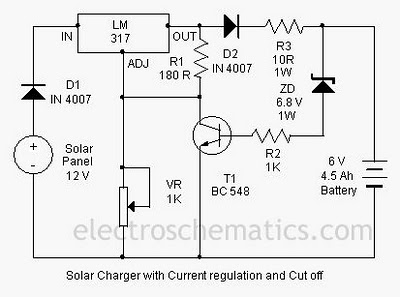
Description: A solar charger circuit is designed to charge lead-acid batteries or nickel-cadmium (Ni-Cd) batteries using solar power. This circuit captures solar energy to charge a 6-volt, 4.5 Ah battery for various applications. It features voltage and current regulation along with a voltage cut-off mechanism. The system utilizes a 12-volt solar panel and a variable voltage regulator IC, specifically the LM317. The solar panel is composed of solar cells, each rated at 1.2 volts, providing a total of 12 volts DC to charge the battery. Load current flows through diode D1 to the LM317 voltage regulator. By adjusting the adjustment pin of the LM317, both voltage and output current can be controlled. A variable resistor (VR) is connected between the adjustment pin and ground to achieve an output voltage suitable for a 9-volt battery. Resistor R3 limits the load current, while diode D2 prevents the battery from discharging. Transistor T1 and zener diode ZD function as a cutoff switch when the battery reaches full charge. Typically, T1 remains off while the battery is under load. When the battery voltage exceeds 6.8 volts, the zener diode conducts, supplying base current to T1, which then turns off the LM317 output, halting the charging process.
The solar charger circuit operates by efficiently converting solar energy into electrical energy, making it suitable for off-grid applications or where conventional power sources are unavailable. The 12-volt solar panel is the primary energy source, composed of multiple solar cells connected in series to achieve the necessary voltage. The LM317 voltage regulator is a versatile component that allows for precise control of the output voltage, which is critical for charging batteries without overcharging, thereby extending their lifespan.
The inclusion of the variable resistor (VR) allows for fine-tuning of the output voltage, accommodating different battery types and ensuring optimal charging conditions. The circuit design prioritizes safety and efficiency, as demonstrated by the use of diode D2 to prevent reverse current flow, which could damage the solar panel or deplete the battery when sunlight is insufficient.
The cutoff mechanism involving transistor T1 and zener diode ZD is a vital feature that protects the battery from overcharging. By monitoring the battery voltage, the circuit can automatically disconnect the charging process when the battery is fully charged, ensuring that the battery maintains its health and performance over time. This automatic cut-off is crucial for maintaining the integrity of lead-acid and Ni-Cd batteries, which are sensitive to overcharging.
In summary, this solar charger circuit is a practical solution for renewable energy applications, providing a reliable means of charging batteries in remote locations or during outdoor activities, while also incorporating essential safety features to protect the battery and enhance its longevity.A solar charger circuit is used to charge lead acid batteries or Ni-Cd with solar power. Circuit harvests solar energy to charge a 6 volt battery 4. 5 Ah battery for various applications. The charger has voltage and current regulation and voltage cut-off facilities. The circuit uses a 12 volt panel solar energy and a variable voltage regula tor IC LM 317. The solar panel consists of solar cells each rated at 1. 2 volts. 12 volt DC is available from the panel to charge the battery. Load current flows through D1 to the voltage regulator IC LM 317. By adjusting the adjustment pin, voltage and output current can be regulated. VR is placed between the adjustment pin and ground to provide an output voltage of 9 volt battery. Restrict resistance R3 load current and the diode D2 prevents the discharge of the battery current. Transistor T1 and zener diode ZD act as a cutoff switch when the battery is full. Usually T1 is off and the battery current load. When the voltage at the terminals of the battery rises above 6. 8 volts, Zener conducts and provides the current basis of T1. Then land becomes the output of the LM 317 to stop charging.
The solar charger circuit operates by efficiently converting solar energy into electrical energy, making it suitable for off-grid applications or where conventional power sources are unavailable. The 12-volt solar panel is the primary energy source, composed of multiple solar cells connected in series to achieve the necessary voltage. The LM317 voltage regulator is a versatile component that allows for precise control of the output voltage, which is critical for charging batteries without overcharging, thereby extending their lifespan.
The inclusion of the variable resistor (VR) allows for fine-tuning of the output voltage, accommodating different battery types and ensuring optimal charging conditions. The circuit design prioritizes safety and efficiency, as demonstrated by the use of diode D2 to prevent reverse current flow, which could damage the solar panel or deplete the battery when sunlight is insufficient.
The cutoff mechanism involving transistor T1 and zener diode ZD is a vital feature that protects the battery from overcharging. By monitoring the battery voltage, the circuit can automatically disconnect the charging process when the battery is fully charged, ensuring that the battery maintains its health and performance over time. This automatic cut-off is crucial for maintaining the integrity of lead-acid and Ni-Cd batteries, which are sensitive to overcharging.
In summary, this solar charger circuit is a practical solution for renewable energy applications, providing a reliable means of charging batteries in remote locations or during outdoor activities, while also incorporating essential safety features to protect the battery and enhance its longevity.A solar charger circuit is used to charge lead acid batteries or Ni-Cd with solar power. Circuit harvests solar energy to charge a 6 volt battery 4. 5 Ah battery for various applications. The charger has voltage and current regulation and voltage cut-off facilities. The circuit uses a 12 volt panel solar energy and a variable voltage regula tor IC LM 317. The solar panel consists of solar cells each rated at 1. 2 volts. 12 volt DC is available from the panel to charge the battery. Load current flows through D1 to the voltage regulator IC LM 317. By adjusting the adjustment pin, voltage and output current can be regulated. VR is placed between the adjustment pin and ground to provide an output voltage of 9 volt battery. Restrict resistance R3 load current and the diode D2 prevents the discharge of the battery current. Transistor T1 and zener diode ZD act as a cutoff switch when the battery is full. Usually T1 is off and the battery current load. When the voltage at the terminals of the battery rises above 6. 8 volts, Zener conducts and provides the current basis of T1. Then land becomes the output of the LM 317 to stop charging.
UNIVERSAL BATTERY CHARGER
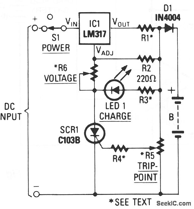
When power is applied to the circuit, SCR1 remains off, resulting in no bias-current path to ground; consequently, the LM317 operates as a current regulator. The LM317 is connected to the battery through steering diode D1, limiting resistor R1, and...
Simple Miniature Motor Controller by LM317
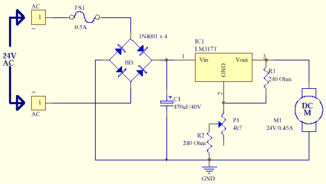
This information pertains to a dosing pump control circuit that utilizes the LM317 integrated circuit (IC). The circuit operates with a power supply of 24V DC and is capable of adjusting the output voltage to 1.25V.
The LM317 is a versatile...
7.2V Battery Replacement Power Supply For Camcorders
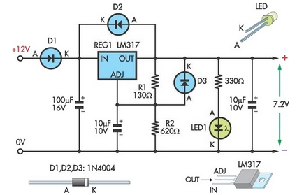
This circuit allows an external 12V sealed lead-acid (SLA) battery to power a camcorder that typically operates with an internal 7.2V battery. Obtaining such batteries for older camcorder models can be challenging and costly. The circuit functions as a standard...
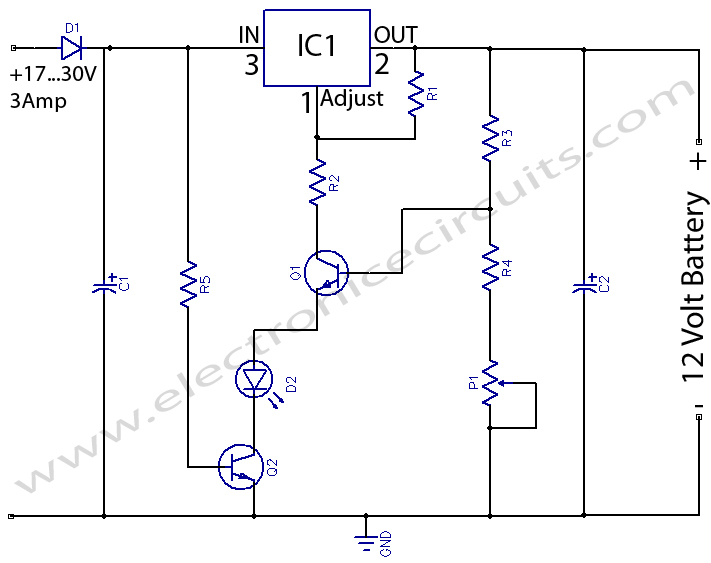
12 Volts Lead Acid Battery Charger
12 Volts Lead Acid Battery Charger Circuit. Apart from serving as a standard battery charger, this circuit is ideal for providing a constant charge to a 12-Volt lead-acid battery.
This 12-Volt lead-acid battery charger circuit is designed to efficiently charge and...
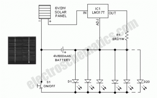
DIY Solar Birdhouse Light
This solar birdhouse light features an economical circuit for a mini solar lighting system. The core component of the circuit is a mini 6V/2W solar panel, which is utilized to charge a 4V/800mAh rechargeable battery. The charging process is managed...
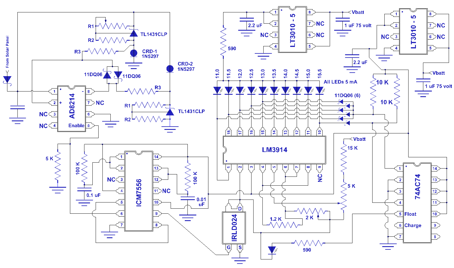
simple mppt solar panel charge controllers
I have been researching the appropriate voltages for charging, particularly regarding this topic.
The proper voltage levels for charging various types of batteries are critical for ensuring efficiency and longevity. For instance, lithium-ion batteries typically require a charging voltage of around...
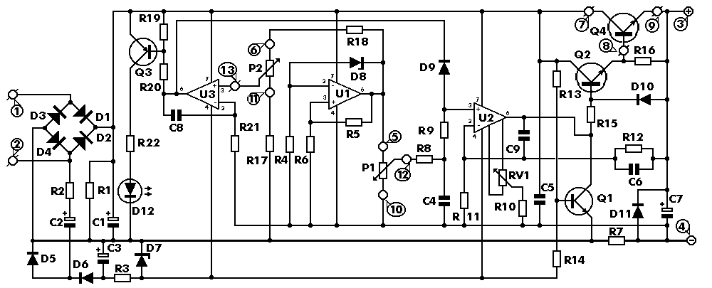
0-30 VDC Stabilized Power Supply with Current Control 0.002-3 A
The circuit begins with a step-down mains transformer featuring a secondary winding rated at 24 V/3 A, which connects across the input points at pins 1 and 2. The quality of the output supply is directly related to the transformer's...
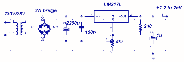
LM317 variable power supply
A truly timeless circuit. LM317 is a versatile and highly efficient 1.2-37V voltage regulator that can provide up to 1.5A of current with a large heat sink. It's ideal for just about any application. Since LM317 is protected against short-circuit,...
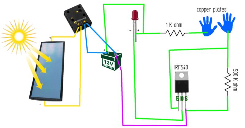
Solar panel circuit
A printed circuit board (PCB) was presented along with a schematic detailing the arrangement of components required for the activation of an LED on the board. The purpose of the PCB is to facilitate planning for the eventual construction of...