


Solar Charger for 6V 4.5Ah Battery
#solar charger
#lead acid battery
#Ni-Cd battery
#voltage regulation
#current regulation
#over voltage cut off
#6V battery
#rechargeable battery
#solar energy
#12V panel
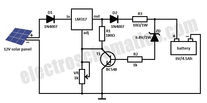
Description: This is a solar charger circuit designed to charge Lead Acid or Ni-Cd batteries using solar energy. The circuit captures solar energy to recharge a 6-volt, 4.5 Ah rechargeable battery for various applications. It includes voltage and current regulation features along with an over-voltage cutoff mechanism. The solar panel provides a 12-volt DC output for charging the battery. The charging current flows through diode D1 to the voltage regulator IC LM317. By adjusting the Adjust pin, both the output voltage and current can be regulated. A variable resistor (VR) is connected between the Adjust pin and ground to set the output voltage to 9 volts for the battery. Resistor R3 limits the charging current, while diode D2 prevents the battery from discharging. Transistor T1 and Zener diode ZD function as a cutoff switch when the battery is fully charged. Under normal conditions, T1 remains off, allowing the battery to receive charging current. When the battery's terminal voltage exceeds 6.8 volts, the Zener diode conducts and provides base current to T1, turning it on and grounding the output of the LM317 to halt charging.
The solar charger circuit operates effectively by utilizing solar panels to convert sunlight into electrical energy. The solar panel generates a nominal output of 12 volts DC, which is suitable for charging a 6-volt battery. The LM317 voltage regulator is crucial in maintaining a steady output voltage during the charging process. The output voltage can be adjusted using the variable resistor (VR) to ensure that the battery receives the appropriate voltage level for optimal charging, typically set at 9 volts in this design.
Diode D1 serves to protect the circuit by allowing current to flow in one direction—into the battery—while preventing reverse current flow that could damage the solar panel. Resistor R3 is strategically placed to limit the charging current, thus preventing overcharging and extending the lifespan of the battery. Diode D2 also plays a critical role in maintaining battery health by preventing discharge when the solar panel is not generating power.
The inclusion of transistor T1 and Zener diode ZD adds an essential safety feature to the circuit. This combination acts as an automatic cutoff switch that disconnects the charging current once the battery reaches a predetermined voltage level of 6.8 volts. This feature is vital for preventing overcharging, which can cause damage to the battery and reduce its overall efficiency and lifespan. When the battery voltage exceeds this threshold, the Zener diode conducts, providing sufficient base current to turn on transistor T1. This action grounds the output of the LM317, effectively stopping the charging process until the battery voltage drops below the cutoff level.
Overall, this solar charger circuit is a well-designed solution for renewable energy applications, providing efficient battery charging while incorporating necessary safety features to protect both the battery and the charging circuit.Here is a solar charger circuit that is used to charge Lead Acid or Ni-Cd batteries using the solar energy power. The circuit harvests solar energy to charge a 6 volt 4. 5 Ah rechargeable battery for various applications. The charger has Voltage and Current regulation and Over voltage cut off facilities. 12 volt DC is available from the panel to ch arge the battery. Charging current passes through D1 to the voltage regulator IC LM 317. By adjusting its Adjust pin, output voltage and current can be regulated. VR is placed between the adjust pin and ground to provide an output voltage of 9 volts to the battery. Resistor R3 Restrict the charging current and diode D2 prevents discharge of current from the battery.
Transistor T1 and Zener diode ZD act as a cut off switch when the battery is full. Normally T1 is off and battery gets charging current. When the terminal voltage of the battery rises above 6. 8 volts, Zener conducts and provides base current to T1. It then turns on grounding the output of LM317 to stop charging.
The solar charger circuit operates effectively by utilizing solar panels to convert sunlight into electrical energy. The solar panel generates a nominal output of 12 volts DC, which is suitable for charging a 6-volt battery. The LM317 voltage regulator is crucial in maintaining a steady output voltage during the charging process. The output voltage can be adjusted using the variable resistor (VR) to ensure that the battery receives the appropriate voltage level for optimal charging, typically set at 9 volts in this design.
Diode D1 serves to protect the circuit by allowing current to flow in one direction—into the battery—while preventing reverse current flow that could damage the solar panel. Resistor R3 is strategically placed to limit the charging current, thus preventing overcharging and extending the lifespan of the battery. Diode D2 also plays a critical role in maintaining battery health by preventing discharge when the solar panel is not generating power.
The inclusion of transistor T1 and Zener diode ZD adds an essential safety feature to the circuit. This combination acts as an automatic cutoff switch that disconnects the charging current once the battery reaches a predetermined voltage level of 6.8 volts. This feature is vital for preventing overcharging, which can cause damage to the battery and reduce its overall efficiency and lifespan. When the battery voltage exceeds this threshold, the Zener diode conducts, providing sufficient base current to turn on transistor T1. This action grounds the output of the LM317, effectively stopping the charging process until the battery voltage drops below the cutoff level.
Overall, this solar charger circuit is a well-designed solution for renewable energy applications, providing efficient battery charging while incorporating necessary safety features to protect both the battery and the charging circuit.Here is a solar charger circuit that is used to charge Lead Acid or Ni-Cd batteries using the solar energy power. The circuit harvests solar energy to charge a 6 volt 4. 5 Ah rechargeable battery for various applications. The charger has Voltage and Current regulation and Over voltage cut off facilities. 12 volt DC is available from the panel to ch arge the battery. Charging current passes through D1 to the voltage regulator IC LM 317. By adjusting its Adjust pin, output voltage and current can be regulated. VR is placed between the adjust pin and ground to provide an output voltage of 9 volts to the battery. Resistor R3 Restrict the charging current and diode D2 prevents discharge of current from the battery.
Transistor T1 and Zener diode ZD act as a cut off switch when the battery is full. Normally T1 is off and battery gets charging current. When the terminal voltage of the battery rises above 6. 8 volts, Zener conducts and provides base current to T1. It then turns on grounding the output of LM317 to stop charging.
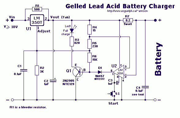
Lead Acid Battery Charger III
This high-performance circuit first quickly starts (and holds) the charge at 2 amp, but as the voltage rises the current will consequently decrease. When the current falls below 150mA, the charger automatically switches to a lower 'Float' voltage to prevent...
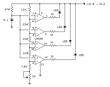
12 Volt Lead Acid Battery Meter Led
In the circuit below, a quad voltage comparator (LM339) is utilized as a simple bar graph meter to indicate the charge condition of a 12-volt lead-acid battery. A 5-volt reference voltage is connected to each of the positive inputs of...
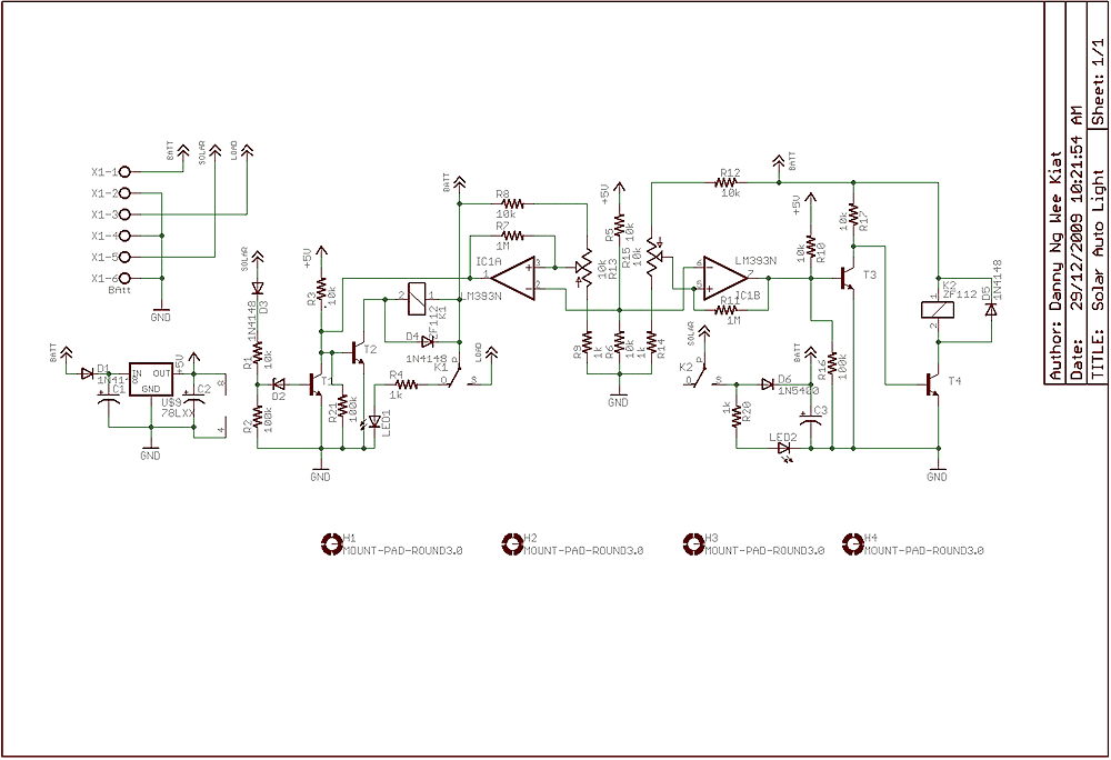
Solar Charger circuit
Few years back, I had been working on a project for solar auto lighting. The light will turn on when the solar panel voltage drop below a set point indicating that it is dark. The detection is done by using...
how does power supply regulate its
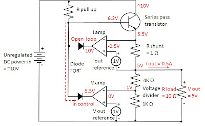
Most power supplies regulate either their output voltage or current at a constant level, depending on the load resistance relative to the power supply's output voltage and current settings. This can be summarized as follows: To accomplish this, most power...
Car Battery Charger
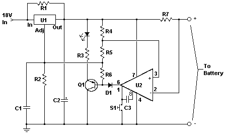
This charger will quickly and easily charge most any lead acid battery. The charger delivers full current until the current drawn by the battery falls to 150 mA. At this time, a lower voltage is applied to finish off and...
Design and making of the stabilized voltage supply of switch
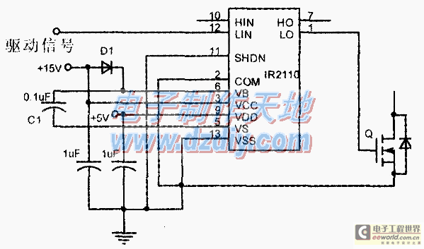
Under the loading condition of the resistance, the output voltage (Uo) variable range is from 30V to 36V, with a maximum output current (Imax) of 2A. When the input voltage (U2) changes from 15V to 21V, the voltage regulation factor...
Voltage Regulators
Until Willow Garage was acquired, there was work as a Web Robotics Engineer. This title reflects a role as a full-stack engineer focused on real-time, distributed robot control. Notable projects include an XML-RPC server and client for Node.js, a deprecated...
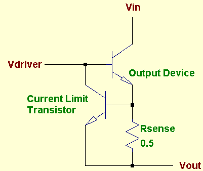
protected
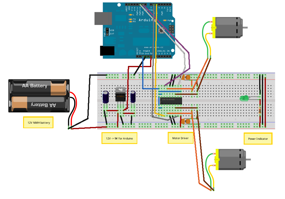
A voltage regulator is designed to provide a fixed voltage to any load. This inherently means it must supply the necessary current through that load to satisfy Ohm's Law, I = V/R. As the resistance (R) approaches zero, such as...
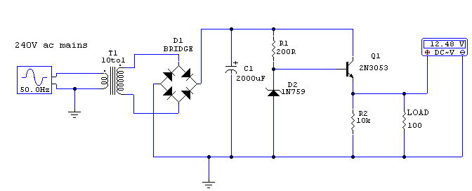
Regulated 12 Volt Supply
This circuit utilizes a 13-volt zener diode (D2) for voltage regulation. Approximately 0.7 volts are dropped across the base-emitter junction of the transistors, resulting in a higher current output of 12.3 volts. The circuit is capable of supplying loads up...