


UC3906 battery charger controller circuit
#UC3906
#lead-acid battery
#charge controller
#voltage regulation
#current control
#charging states
#battery management
#sealed battery
#temperature monitoring
#power management
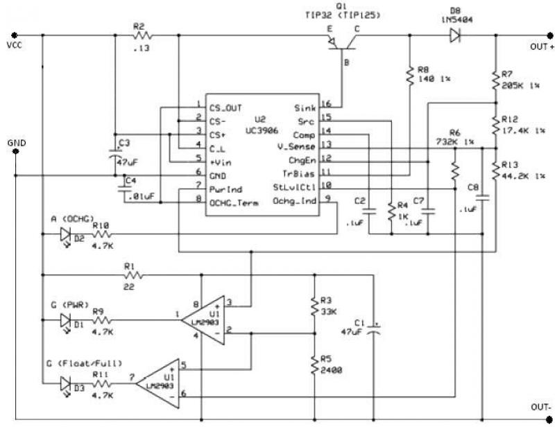
Description: The UC3906 battery charger circuit controller includes all necessary circuitry to manage the charge and hold cycles for sealed lead-acid batteries. This circuit is specifically designed to deliver the appropriate charging voltage and current based on the battery's temperature and state of charge. The UC3906 monitors and regulates both the output voltage and current through three distinct charge states.
The UC3906 features separate voltage loop and current limit amplifiers that adjust the output voltage and current levels in the charger by controlling the onboard driver. The circuit requires a DC input voltage ranging from 18 to 22 volts. Three optical LED indicators display the charge state. The IC is configured to provide three charge states: Bulk charge, where the charger operates in a constant-current mode until the battery reaches the programmed full-charge voltage; Overcharge, where the charger switches to overcharge mode to ‘top-off’ the battery once the full-charge voltage is reached; and Float charge, which occurs when the current decreases to the minimum overcharge current, signaling the charger to enter float charge mode.
The UC3906 battery charger circuit is an efficient solution for managing the charging process of sealed lead-acid batteries. The integration of separate voltage and current control loops allows for precise regulation of the output parameters, ensuring optimal charging conditions. The necessity for a DC input voltage of 18 to 22 volts is critical, as it provides the required headroom for the charging process.
The three charge states are designed to accommodate the various stages of battery charging, enhancing battery longevity and performance. During the Bulk charge phase, the constant-current mode allows for rapid charging until the target voltage is achieved. Transitioning to the Overcharge state prevents the battery from becoming undercharged by providing a slight additional charge to ensure full capacity. Finally, the Float charge mode maintains the battery's charge without overloading it, which is crucial for long-term storage and usage.
The use of optical LED indicators not only enhances user interface but also provides real-time feedback on the charging status, allowing users to monitor the charging process easily. This comprehensive approach to battery management ensures that the UC3906 charger circuit can effectively extend the life of sealed lead-acid batteries while maintaining safety and efficiency throughout the charging cycle.This UC3906 battery charger circuit controller contains all of the necessary circuitry to control the charge and hold cycle for sealed lead-acid batteries. The UC3906 battery charger circuit is specifically designed to provide the proper charging voltage and current determined by the temperature and state of charge of the battery.
The UC3906 battery charger circuit controller monitor and control both the output voltage and current of the charger through three separate charge states . UC3906 has separate voltage loop and current limit amplifiers which regulate the output voltage and current levels in the charger by controlling the onboard driver.The charger circuit requires 18 to 22 volts DC input. Three optical ( LED ) indicators show the charge state . This IC is configured to provide three charge states: Bulk charge – the charger operates in a constant-current charge mode until the battery reaches the programmed full-charge voltage.
Overcharge – when the voltage reaches the programmed full-charge voltage, the charger switches to overcharge mode to ‘top-off’ the battery. Float charge – when the current decreases to the minimum overcharge current, the charger enters the float charge mode.
The UC3906 features separate voltage loop and current limit amplifiers that adjust the output voltage and current levels in the charger by controlling the onboard driver. The circuit requires a DC input voltage ranging from 18 to 22 volts. Three optical LED indicators display the charge state. The IC is configured to provide three charge states: Bulk charge, where the charger operates in a constant-current mode until the battery reaches the programmed full-charge voltage; Overcharge, where the charger switches to overcharge mode to ‘top-off’ the battery once the full-charge voltage is reached; and Float charge, which occurs when the current decreases to the minimum overcharge current, signaling the charger to enter float charge mode.
The UC3906 battery charger circuit is an efficient solution for managing the charging process of sealed lead-acid batteries. The integration of separate voltage and current control loops allows for precise regulation of the output parameters, ensuring optimal charging conditions. The necessity for a DC input voltage of 18 to 22 volts is critical, as it provides the required headroom for the charging process.
The three charge states are designed to accommodate the various stages of battery charging, enhancing battery longevity and performance. During the Bulk charge phase, the constant-current mode allows for rapid charging until the target voltage is achieved. Transitioning to the Overcharge state prevents the battery from becoming undercharged by providing a slight additional charge to ensure full capacity. Finally, the Float charge mode maintains the battery's charge without overloading it, which is crucial for long-term storage and usage.
The use of optical LED indicators not only enhances user interface but also provides real-time feedback on the charging status, allowing users to monitor the charging process easily. This comprehensive approach to battery management ensures that the UC3906 charger circuit can effectively extend the life of sealed lead-acid batteries while maintaining safety and efficiency throughout the charging cycle.This UC3906 battery charger circuit controller contains all of the necessary circuitry to control the charge and hold cycle for sealed lead-acid batteries. The UC3906 battery charger circuit is specifically designed to provide the proper charging voltage and current determined by the temperature and state of charge of the battery.
The UC3906 battery charger circuit controller monitor and control both the output voltage and current of the charger through three separate charge states . UC3906 has separate voltage loop and current limit amplifiers which regulate the output voltage and current levels in the charger by controlling the onboard driver.The charger circuit requires 18 to 22 volts DC input. Three optical ( LED ) indicators show the charge state . This IC is configured to provide three charge states: Bulk charge – the charger operates in a constant-current charge mode until the battery reaches the programmed full-charge voltage.
Overcharge – when the voltage reaches the programmed full-charge voltage, the charger switches to overcharge mode to ‘top-off’ the battery. Float charge – when the current decreases to the minimum overcharge current, the charger enters the float charge mode.
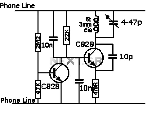
automatic 12v lead acid battery charger
This design is for a charger circuit suitable for lead-acid batteries, including flooded, gel, and AGM types. The circuit features a simple design. The automatic function means that this charger will stop charging automatically when the battery voltage reaches a...
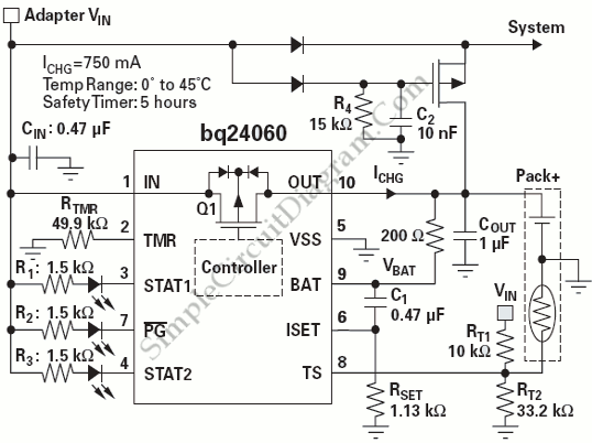
Power Path Management Battery Charger
Powering the system is required by many applications while charging the battery simultaneously. Interaction between the system and charger may result in a...
Power management in electronic systems is critical, particularly in applications that necessitate simultaneous operation and battery charging. This...
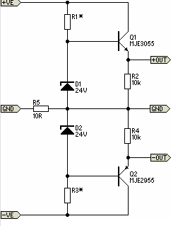
Simple Pre-Regulator
There will be many occasions when it is beneficial to utilize the P05 supply module sourced from a higher voltage supply. For instance, this could be advantageous when integrating balanced inputs.
The P05 supply module is designed to facilitate the conversion...
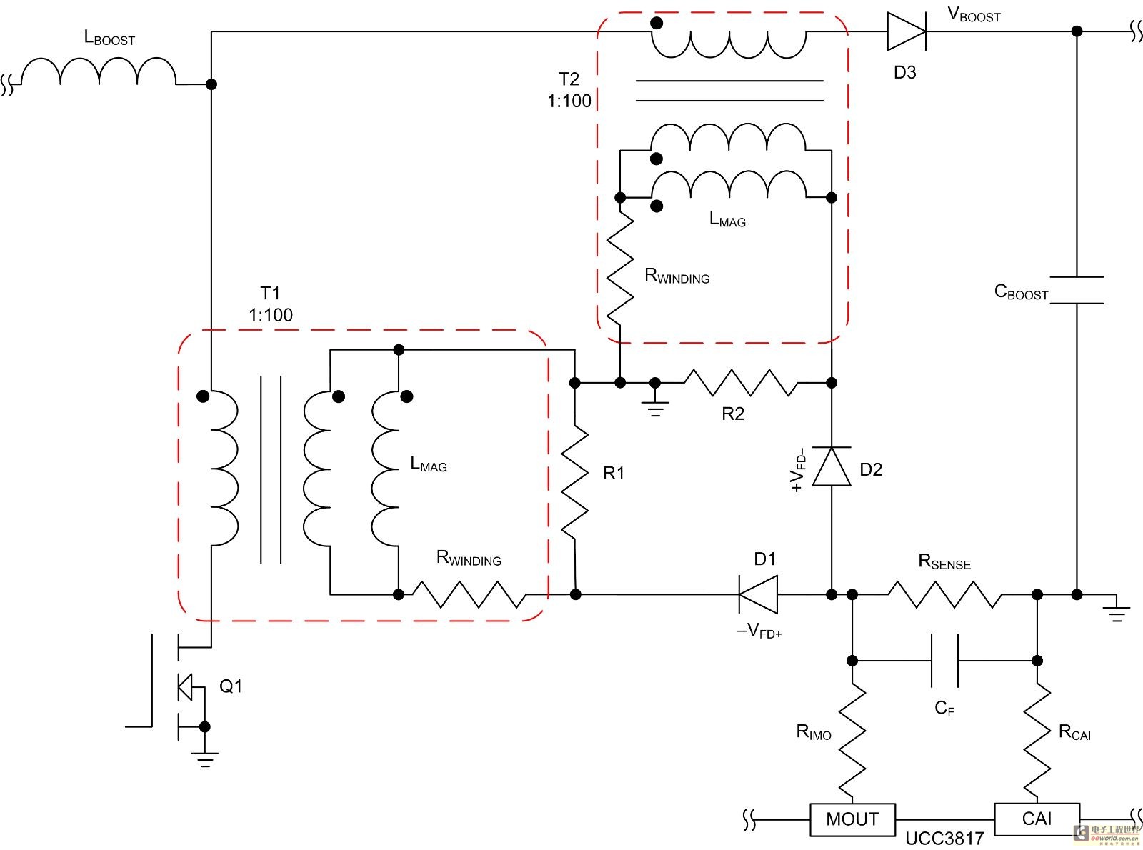
The electric current of mode control of the average current measures the circuit design of the voltage transformer
Mode control of the average current (CMC) is necessary to regulate the overall waveform of electric current during the rebuilding cycle. This text recommends selecting specific parameters related to the voltage transformer and outlines steps for designing a circuit that...
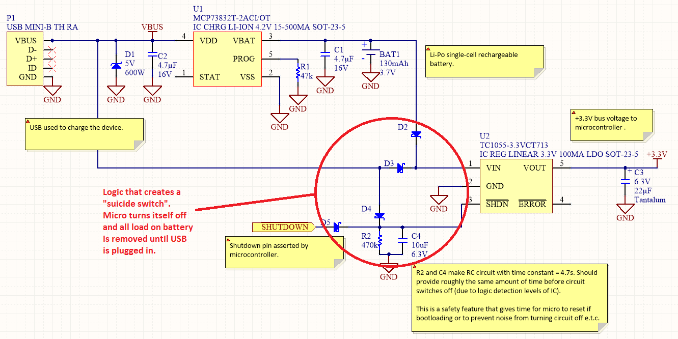
Power Management
Overview Disabling Sections of a Circuit The "Suicide Switch" Overview Power management is a significant design consideration for battery-powered devices.
Power management is a crucial aspect of circuit design, particularly in battery-powered applications where energy efficiency directly impacts the operational lifespan...
Power Path Management Battery Charger
Powering the system is required by many applications while charging the battery simultaneously. Interaction between the system and charger may result in a...
Power management in electronic systems is critical, particularly in applications that necessitate simultaneous operation and battery charging. This...
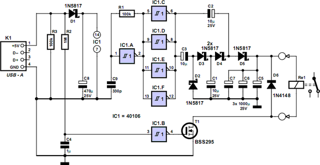
Computer Off Switch
How often does it happen that a user shuts down Windows and then forgets to turn off the computer? This circuit automates that process. After Windows is shut down, a click occurs a second later, disconnecting the PC from the...
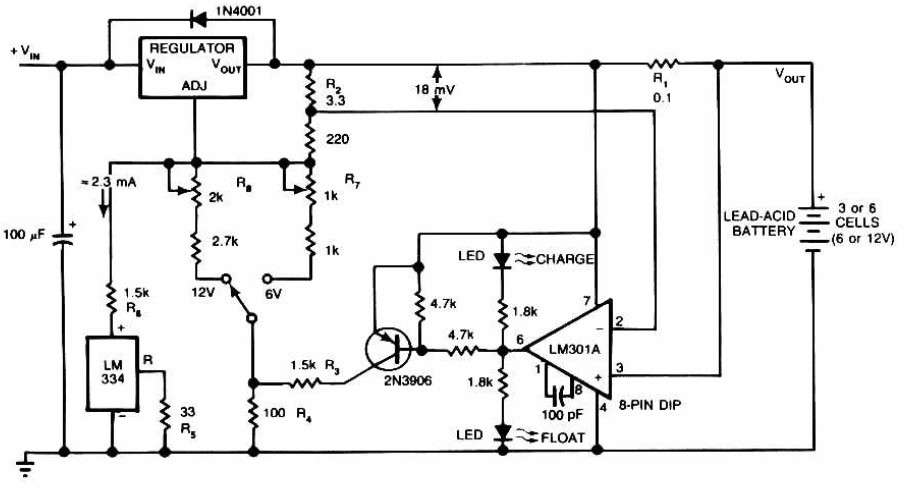
Lead-Acid Battery Charger circuit diagram
Lead-Acid Battery Charger circuit diagram. The LM301A compares the voltage drop across R1 with an 18 mV reference set by R2. The comparator's output controls the voltage regulator, forcing it to produce the lower float voltage when the battery-charging current,...
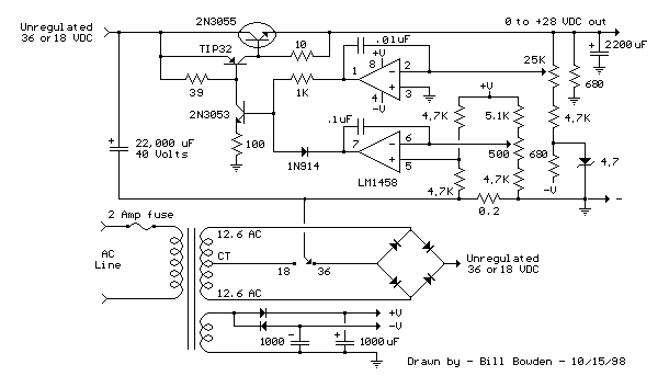
Current and Variable Voltage Power Supply
Another adjustment of application operational amplifiers to adapt a power supply is apparent below. The power supply requires an additional adjustment to supply the op-amps with a bipolar voltage (+/- 8 volts), and the negative voltage is also used to...