


Carrier-Operated Relay
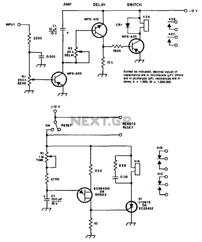
Description: A circuit diagram illustrates a COR/CAS circuit designed for repeater applications. CR1 is identified as a silicon diode, while relay 2 can be any relay with a 12-V coil, with a reed relay being preferred for longevity. Resistor R2 determines the duration for which K2 remains closed after the input voltage is lost (referred to as hang time). A timer circuit is also depicted, with specified values for R1 and C1 designed to allow timing up to approximately four minutes. C1 should be a low-leakage capacitor, and Q1 is a silicon-controlled rectifier, specifically an ECG-5452 or a compatible component. K1 can be any miniature relay featuring a 12-volt coil. The timer resets when there is a temporary interruption in the supply voltage, and the switch must be in the reset position for remote reset functionality to operate. This circuit is powered by the detector output from a receiver, and a delay circuit is integrated to ensure that the relay remains closed for a specified duration after the carrier output from the receiver ceases.
The COR/CAS circuit serves as a crucial component in repeater systems, allowing for effective signal management and relay control. The silicon diode CR1 functions as a rectifier, ensuring that only the appropriate current flows through the circuit, protecting sensitive components from reverse voltage. The choice of relay 2, preferably a reed relay, enhances the reliability and longevity of the circuit due to its low power consumption and minimal wear over time.
The timing aspect of the circuit is facilitated by resistor R2 and capacitor C1, which together form an RC timing network. The values of R1 and C1 are critical in determining the timing interval, with the configuration allowing for adjustments to achieve a hang time of up to four minutes. The use of a low-leakage capacitor for C1 is paramount, as it minimizes the loss of charge, thereby ensuring accurate timing and reliable operation.
The silicon-controlled rectifier Q1 plays a vital role in controlling the relay K1. When triggered, Q1 allows current to flow through the relay coil, energizing it and closing the contacts. The choice of a miniature relay with a 12-volt coil for K1 ensures compatibility with the circuit's power supply while maintaining a compact design.
The reset functionality of the timer is designed to be sensitive to supply voltage interruptions. This feature is essential for maintaining the integrity of the repeater operation, as it allows for automatic reset conditions after temporary power loss. The remote reset capability is an added benefit, enabling external control over the timer function, provided that the switch remains in the reset position.
Overall, this COR/CAS circuit is engineered for efficiency and reliability in repeater applications, integrating essential components that work in harmony to achieve desired operational outcomes. The inclusion of a delay circuit ensures that the relay remains engaged for a defined period following signal loss, contributing to the overall robustness of the repeater system. A shows a COR/CAS circuit for repeater use. CR1 is a silicon diode. 2 may be any relay with a 12-V coil (a long-life reed relay is best). R2 sets the length of time that K2 remains closed after the input voltage disappears (hang time). shows a timer circuit. Values shown for Rl and CI should provide timing up to four minutes or so. CI should be a low-leakage capacitor; Ql is a silicon-controlled rectifier, ECG-5452 or equivalent. Kl may be any miniature relay with a 12-volt coil. The timer is reset when the supply voltage is momentarily interrupted. The switch must be in the reset position for the remote reset to work. This circuit operates from the detector output of a receiver. A delay circuit is included so that the relay stays closed for a time period after the carrier output from the receiver disappears.
The COR/CAS circuit serves as a crucial component in repeater systems, allowing for effective signal management and relay control. The silicon diode CR1 functions as a rectifier, ensuring that only the appropriate current flows through the circuit, protecting sensitive components from reverse voltage. The choice of relay 2, preferably a reed relay, enhances the reliability and longevity of the circuit due to its low power consumption and minimal wear over time.
The timing aspect of the circuit is facilitated by resistor R2 and capacitor C1, which together form an RC timing network. The values of R1 and C1 are critical in determining the timing interval, with the configuration allowing for adjustments to achieve a hang time of up to four minutes. The use of a low-leakage capacitor for C1 is paramount, as it minimizes the loss of charge, thereby ensuring accurate timing and reliable operation.
The silicon-controlled rectifier Q1 plays a vital role in controlling the relay K1. When triggered, Q1 allows current to flow through the relay coil, energizing it and closing the contacts. The choice of a miniature relay with a 12-volt coil for K1 ensures compatibility with the circuit's power supply while maintaining a compact design.
The reset functionality of the timer is designed to be sensitive to supply voltage interruptions. This feature is essential for maintaining the integrity of the repeater operation, as it allows for automatic reset conditions after temporary power loss. The remote reset capability is an added benefit, enabling external control over the timer function, provided that the switch remains in the reset position.
Overall, this COR/CAS circuit is engineered for efficiency and reliability in repeater applications, integrating essential components that work in harmony to achieve desired operational outcomes. The inclusion of a delay circuit ensures that the relay remains engaged for a defined period following signal loss, contributing to the overall robustness of the repeater system. A shows a COR/CAS circuit for repeater use. CR1 is a silicon diode. 2 may be any relay with a 12-V coil (a long-life reed relay is best). R2 sets the length of time that K2 remains closed after the input voltage disappears (hang time). shows a timer circuit. Values shown for Rl and CI should provide timing up to four minutes or so. CI should be a low-leakage capacitor; Ql is a silicon-controlled rectifier, ECG-5452 or equivalent. Kl may be any miniature relay with a 12-volt coil. The timer is reset when the supply voltage is momentarily interrupted. The switch must be in the reset position for the remote reset to work. This circuit operates from the detector output of a receiver. A delay circuit is included so that the relay stays closed for a time period after the carrier output from the receiver disappears.
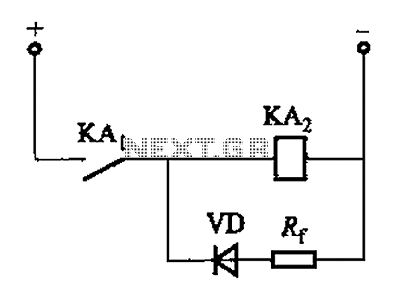
DC relay delayed release circuit 2 b
The circuit depicted in Figure 6-24 includes a relay coil with both ends connected in parallel to a resistor (Rf) or an auxiliary diode (VD). This configuration is intended to enhance power after a short circuit occurs in the coil...
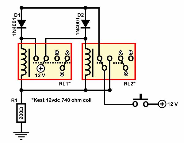
build relay toggle switch
Half of RL1 and RL2 manage the switching mechanism, while the other half connects to an application. The relays operate at 200 ohms above ground, with one terminal referenced to positive voltage, which deactivates them. RL1, when off, applies a...
Reducing Relay Power Consumption
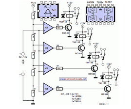
This circuit demonstrates that microprocessors, personal computers, and the latest ultra-accurate digital-to-analog converters (DACs) are excessive for the task of sequentially controlling four relays.
The circuit utilizes a simple microcontroller or a basic timer IC to manage the operation of four...
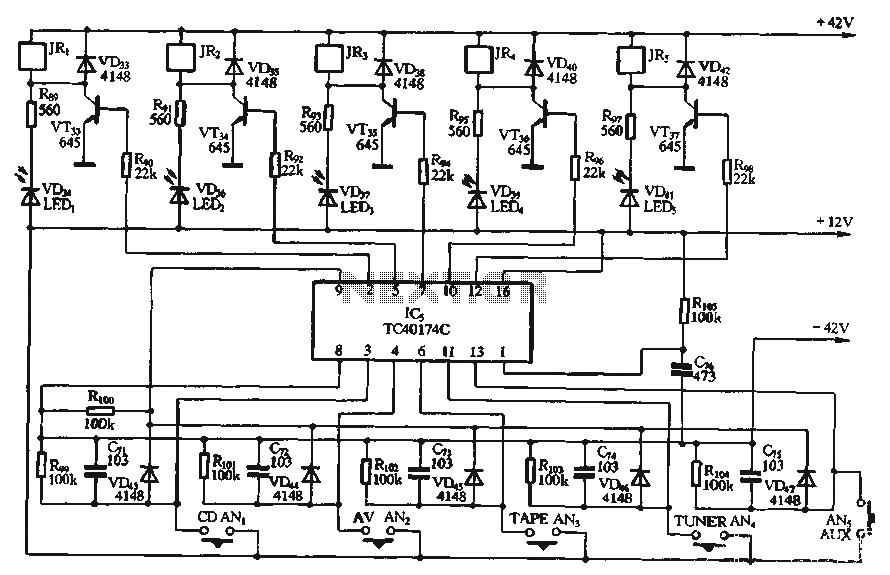
Input switching circuit
A relay is controlled by a closed circuit in a digital logic setup, utilizing a touch input switching circuit.
The described circuit involves a relay that operates based on a closed circuit condition within a digital logic framework. The relay serves...
relay circuit diagram
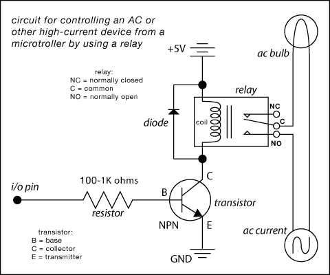
Here are some circuit diagrams for driving relays from a microcontroller. Ensure the use of a 5-volt relay (this refers to the coil, not the load circuit) and verify that the relay has a sufficient rating for the load being...
Pulsing Relay
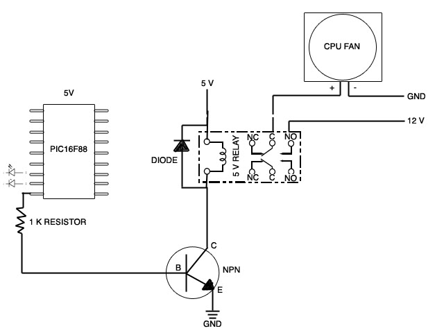
A new member has joined the forum seeking assistance with a project involving the control of a CPU fan using a relay that is triggered by a stretch sensor. The circuit is currently set up, but the stretch sensor is...
relay Do I need a protection diode here
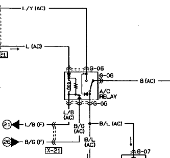
An automotive relay is being analyzed, which exhibits a more complex wiring configuration than typical relays. The diagram indicates that the B/G line maintains a high signal if certain conditions are met, specifically when the engine temperature is excessively high,...
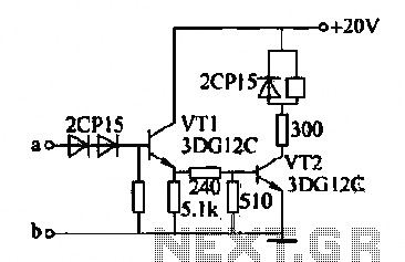
Relay control circuit
The motor winding is configured with delta transposition capacitance, designated as cl-C-3G. It operates as a DC LAN speed generator and is associated with a three-phase asynchronous motor, which is coaxially connected through a field winding powered by a 10V...
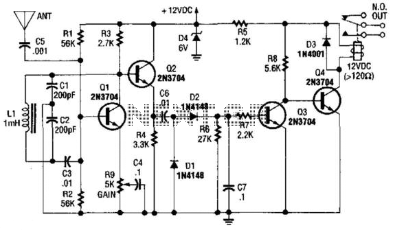
Relay Output Proximity Sensor
Q1 is used as an oscillator operating at approximately 300 kHz. Resistor R9 is configured to allow the oscillator to initiate its operation. An object near the antenna will load the circuit, causing the oscillations to cease. This change is...