


Fiber-optic link
#fiber-optic
#analog driver
#receiver
#transimpedance amplifier
#LED
#optical communication
#3 MHz
#transmitter
#modulation
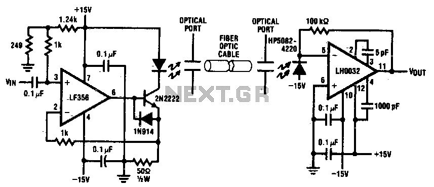
Description: Fiber optic applications require analog drivers and receivers operating in the megahertz region. This complete analog transmission system is suitable for optical communication applications up to 3 MHz. The transmitter LED is normally biased at 50 mA operating current. The input is capacitively coupled and ranges from 0 to 5 V, modulating the LED current from 0 to 100 mA. The receiver circuit is configured as a transimpedance amplifier. The photodiode with 0 A/W responsivity generates a 50 mV signal at the receiver output for 1 µW of light input.
The described analog transmission system for fiber optic applications operates effectively within the frequency range of up to 3 MHz, making it suitable for various optical communication tasks. The system comprises a transmitter and a receiver, where the transmitter utilizes a light-emitting diode (LED) that is typically biased at a constant current of 50 mA. This biasing ensures that the LED operates efficiently, providing a stable light output necessary for reliable data transmission.
The input signal to the transmitter is capacitively coupled, allowing for the modulation of the LED current based on the input voltage, which can range from 0 to 5 V. This modulation capability is crucial as it enables the LED to vary its output current between 0 and 100 mA, effectively encoding the input signal into light pulses for transmission through the fiber optic medium.
On the receiving end, the circuit is designed as a transimpedance amplifier, which is crucial for converting the small photocurrent generated by the photodiode into a measurable output voltage. The photodiode is characterized by a responsivity of 0 A/W, indicating its efficiency in converting light into electrical signals. For an input light power of 1 µW, the photodiode generates a corresponding output signal of 50 mV at the receiver. This voltage output can then be processed further to retrieve the transmitted information.
Overall, this analog transmission system is an essential component in fiber optic communication, facilitating high-frequency data transfer with precise modulation and demodulation capabilities. Its design ensures optimal performance in transmitting and receiving signals over optical fibers.Fiber Optic applications require analog drivers and receivers operating in the megahertz region. This complete analog transmission system is suitable for optical communication applications up to 3 MHz. The transmitter LED is normally biased at 50 mA operating current. The input is capacitively coupled and ranges from 0 to 5 V, modulating the LED current from 0 to 100 mA.
The receiver circuit is configured as a transimpe-danee amplifier The photodiode with 0 amp per watt responsivity generates a 50 mV signal at the receiver output for 1 /iW of light input.
The described analog transmission system for fiber optic applications operates effectively within the frequency range of up to 3 MHz, making it suitable for various optical communication tasks. The system comprises a transmitter and a receiver, where the transmitter utilizes a light-emitting diode (LED) that is typically biased at a constant current of 50 mA. This biasing ensures that the LED operates efficiently, providing a stable light output necessary for reliable data transmission.
The input signal to the transmitter is capacitively coupled, allowing for the modulation of the LED current based on the input voltage, which can range from 0 to 5 V. This modulation capability is crucial as it enables the LED to vary its output current between 0 and 100 mA, effectively encoding the input signal into light pulses for transmission through the fiber optic medium.
On the receiving end, the circuit is designed as a transimpedance amplifier, which is crucial for converting the small photocurrent generated by the photodiode into a measurable output voltage. The photodiode is characterized by a responsivity of 0 A/W, indicating its efficiency in converting light into electrical signals. For an input light power of 1 µW, the photodiode generates a corresponding output signal of 50 mV at the receiver. This voltage output can then be processed further to retrieve the transmitted information.
Overall, this analog transmission system is an essential component in fiber optic communication, facilitating high-frequency data transfer with precise modulation and demodulation capabilities. Its design ensures optimal performance in transmitting and receiving signals over optical fibers.Fiber Optic applications require analog drivers and receivers operating in the megahertz region. This complete analog transmission system is suitable for optical communication applications up to 3 MHz. The transmitter LED is normally biased at 50 mA operating current. The input is capacitively coupled and ranges from 0 to 5 V, modulating the LED current from 0 to 100 mA.
The receiver circuit is configured as a transimpe-danee amplifier The photodiode with 0 amp per watt responsivity generates a 50 mV signal at the receiver output for 1 /iW of light input.
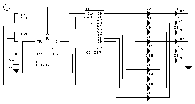
Knightrider lights for model carss
This simple circuit drives six LEDs in a "Knightrider scanner mode." Power consumption primarily depends on the type of LEDs used, particularly when employing a 7555 (555 CMOS version).
The circuit operates by sequentially illuminating the LEDs to create a visual...
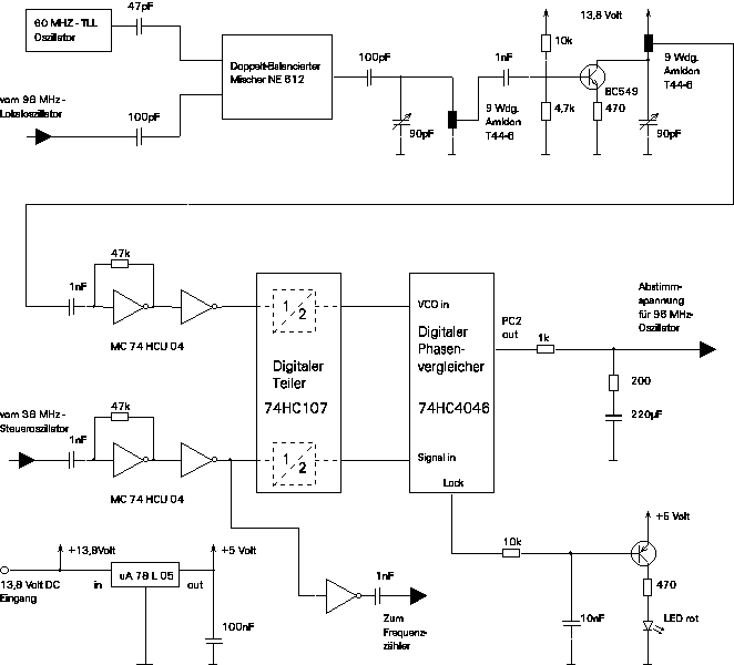
Circuit diagramms of the 144 SBB/RX - Receiver
To comprehend the interconnections between the following circuits, it is essential to first review the concept chapter. It is at the discretion of the user to select one or two of these circuits for personal development. The discussion begins with...
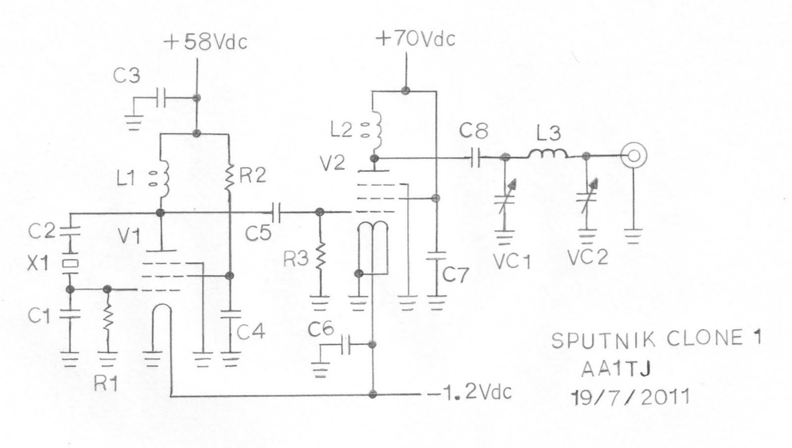
Sputnik QSO Party Transmitter Prototype
This document describes a prototype transmitter for the Sputnik QSO Party. The RF output power is 450 mW, with 70 V DC at 14.4 mA on the V2 anode. The screen current (G2) for V2 is 1.6 mA, while the...
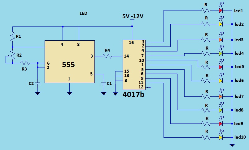
LED light chaser using 4017
This is a LED sequencer circuit where 10 LEDs light up and turn off sequentially, creating a chasing effect. This simple circuit is suitable for designing lighting decorations on Christmas trees. It can also be used for lighting animations by...
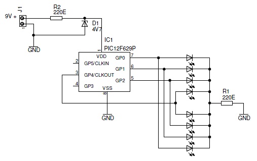
knight Rider 2
This project describes a light effect that is similar to the one of the car in the TV series "Knight Rider."
The light effect project emulates the iconic scanning LED light sequence featured in the "Knight Rider" television series. The design...
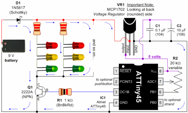
LED Pumpkin Candles for Colorful Halloween Jack-O-Lanterns
Discrete blinking LEDs are convenient, but the blink rate and duration are not configurable. Experimentation with transistors, resistors, and capacitors was attempted to modify the blinking LED behavior. Ultimately, the abundance of additional electronic components led to the conclusion that...
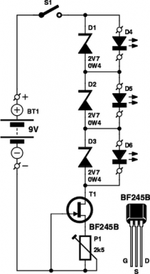
LED Tester
These small electronic lamps are incredibly useful and have a remarkably long lifespan. Approximately 40 years after Nick Holonyak developed the first LED, they have become essential components in various applications. Any dedicated electronics hobbyist typically keeps a selection of...
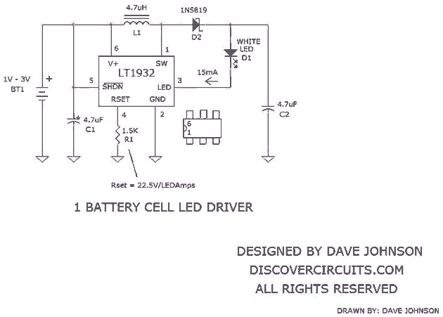
White LED is Powered by Joule thief
Numerous white LED driver circuits are available, with a well-known design called the Joule Thief capable of powering a single white LED from a 1.2V or 1.5V battery cell. Most of these circuits utilize one or two transistors to create...
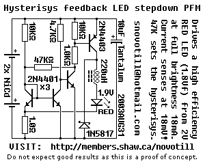
LED stepdown power supply
Below is a proof of concept circuit which needs improvement. The part values shown will run a high efficiency red LED with a Vf of 1.9V from only 2 nicads, right down to 2 volts. For a white LED you...