


IR InfraRed Communication circuit
#IR communication
#infrared
#data transmission
#remote signaling
#packet transmission
#wireless communication
#sensor feedback
#event notification
#real-time monitoring
#security alert
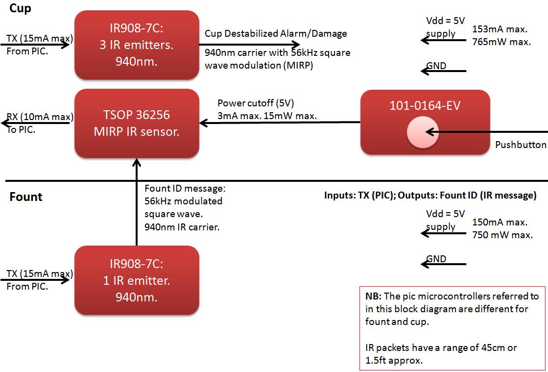
Description: The founts must notify the server when the cup is taken from the fount or when the opponent's cup is poured into the team's cup. The implementation of the actual pouring action is at the discretion of the team. If the cup is removed and not connected to a player's HIU within 5 seconds, it will destabilize and emit harmful IR packets in all directions periodically every 2 seconds until it is either returned to its fount or connected to a player's HIU. Both the pouring action and the cup's instability were managed using the IR block. An IR LED on the fount emitted an 8-bit data package at a constant rate. To initiate pouring, the lid must be removed, and a pushbutton pressed to enable reception, which serves as a precaution against interference from the MAGE system. The MAGE IR Protocol (MIRP) was adopted, necessitating that internal communications related to cup pouring would not interfere with the MAGE system. Consequently, the packets were designed for short-range communication (1.5 feet). Additionally, IR LEDs on the cup's exterior would transmit packets when the cup destabilized after being removed from the fount and not connected to a player's HIU. Initially, long-range IR emission was considered for the cups, but this was ultimately deemed unnecessary. The software was adapted from code available on the MAGE development website, but modifications were required to accommodate the newer PIC microcontroller, which lacked support for many libraries and functions used in the original IR code. The code was extensively revised to function correctly with the hardware and to respond to interrupts without halting the main function during data transmission or reception.
Research into gyroscopes was initially conducted, but the decision was made to discard this option due to the complexity of integrating angle changes over time, which could lead to instability and recalibration issues. The exploration then shifted to accelerometers, which were found to be capable of measuring tilt in addition to acceleration. A one-axis accelerometer was chosen for simplicity, with the intent to signal the PIC when the gravity reading decreased by a certain percentage, indicating that the cup had been tilted. However, it was later recognized that different readings could occur based on the cup's movement, prompting consideration of two- and three-axis accelerometers for improved precision in pouring detection. The use of three inputs would necessitate either three analog-to-digital converters or multiple digital pins, and there were concerns about detecting whether the cup was being tilted above the fount, which could allow players to cheat.
The adoption of infrared communication was favored due to its proximity requirement, ensuring that players would need to be close to the fount. This method would transmit information to the PIC without consuming excessive pins or peripherals. Concerns regarding potential crosstalk between the internal communication and the MAGE system led to considerations of using different modulation frequencies or carrier wavelengths, both of which were feasible. However, maintaining compatibility with the MAGE system was prioritized to allow for future modifications of the product. For instance, the fount and cup could be adapted to pour onto players or weapons to provide health or inflict damage, or to mix different founts to create special formulas.
To comply with MIRP standards while minimizing crosstalk, the IR communication receiver was integrated within the cup/stine, ensuring that no messages would be received until the lid was raised. Low-range IR emitters were selected to limit the range of IR data packets to no more than 2 feet, achieving an effective range of approximately 1.5 feet from various models. This design ensures that the system operates efficiently while adhering to the necessary communication protocols.The founts must notify the server in the event of the cup being taken from the fount or the opponent`s cup being poured into the team`s cup. It is up to the team how the actual pouring action is implemented If the cup is removed and not connected to a player`s HIU within 5 seconds, it will destabilize and fire deadly IR packets in all dir
ection periodically every 2 seconds until it is either returned to its fount or connected to a player`s HIU . Both the pouring action and the cup instability were accomplished with the IR block. On the fount there was an IR LED that emitted an 8 bit package at a constant rate. When the cup was going to pour, the lid had to be removed and the pushbutton pressed to enable reception.
These were extra measures taken to ensure that we would not get interference from the MAGE system. As we decided to use the MAGE IR Protocol (MIRP), we also had to ensure that our internal communication (cup pouring action) would not interfere with the MAGE system. For this, we decided to make the packets short range (1. 5 feet). Additionally, there were IR LEDs on the outside of the cup that would fire packets when the cup would destabilize because it had been removed from the fount and not plugged into a player`s HIU.
At first, I wanted to have long range IR emission on the cups, but decided against it since it wasn`t a requirement. The software was based upon the code on the MAGE development website. Our pic microcontroller is fairly new and did not support many of the libraries and functions used by the IR code on the website.
Because of this, it was changed heavily to work correctly with our hardware and to respond to interrupts rather than stop the main function when sending or receiving. A gyroscope was the first topic that I researched. I discarded it because the gyroscopes` output was an indication of the change in angle per unit of time.
To know the tilt I might have had to integrate. We know that accumulating functions, such as the integral, have the tendency to be unstable. There was also a possibility of having to recalibrate the cup on power-up. My research then took me to accelerometers, although I originally thought it would only measure acceleration I found that it could be used as tilt indicators as well. The accelerometer has a given offset because it measures gravity (F=ma, W=mg) as an acceleration. I wanted to keep it simple so I thought of using just a one-axis accelerometer. The plan was to have a signal go to the PIC when the gravity reading had decremented in a certain percentage and therefore meant that the cup had been turned.
It later came to mind that a player might indeed be able to get a different reading from the accelerometer based on the movement the cup is submitted to. Two and three-axis accelerometers were considered later to add precision to the pouring. Because of the three inputs from the accelerometer, I would either need 3 analog to digital converters or several digital pins to receive my information.
It would also not be able to detect if the cup was being turned above the fount or not, and then players could cheat and get points before making it to the fount. I then moved on to infrared communication. It would require proximity so the player would have to be close to the fount. It would also send information to the PIC without taking up too many pins or peripherals. A question was raised about crosstalk between our internal communication and the mage system. A different frequency for the modulating square wave or a different wavelength for the carrier was considered.
They were both feasible and not difficult to implement. However, I wanted to keep the communication with the MAGE system so as to provide more applications for our circuit than that of the minimum. By adhering to MIRP, there is a possibility that the end-user may modify our product in the future to be able to play the game differently.
For example, the fount and the cup can be modified to pour onto players or weapons to provide health or inflict damage. It could also be modified to get energy from different founts and mix them in a fount to obtain special formulas.
To maintain MIRP standards and still reduce the crosstalk, the receiver for the IR communication was put inside the cup/stine such that no messages will be received until the lid has been raised. To not harm the MAGE system, very low-range IR emitters were considered so that the IR data packets do not go further than 2ft.
From the different models, about a 1. 5ft range was achieved.
Research into gyroscopes was initially conducted, but the decision was made to discard this option due to the complexity of integrating angle changes over time, which could lead to instability and recalibration issues. The exploration then shifted to accelerometers, which were found to be capable of measuring tilt in addition to acceleration. A one-axis accelerometer was chosen for simplicity, with the intent to signal the PIC when the gravity reading decreased by a certain percentage, indicating that the cup had been tilted. However, it was later recognized that different readings could occur based on the cup's movement, prompting consideration of two- and three-axis accelerometers for improved precision in pouring detection. The use of three inputs would necessitate either three analog-to-digital converters or multiple digital pins, and there were concerns about detecting whether the cup was being tilted above the fount, which could allow players to cheat.
The adoption of infrared communication was favored due to its proximity requirement, ensuring that players would need to be close to the fount. This method would transmit information to the PIC without consuming excessive pins or peripherals. Concerns regarding potential crosstalk between the internal communication and the MAGE system led to considerations of using different modulation frequencies or carrier wavelengths, both of which were feasible. However, maintaining compatibility with the MAGE system was prioritized to allow for future modifications of the product. For instance, the fount and cup could be adapted to pour onto players or weapons to provide health or inflict damage, or to mix different founts to create special formulas.
To comply with MIRP standards while minimizing crosstalk, the IR communication receiver was integrated within the cup/stine, ensuring that no messages would be received until the lid was raised. Low-range IR emitters were selected to limit the range of IR data packets to no more than 2 feet, achieving an effective range of approximately 1.5 feet from various models. This design ensures that the system operates efficiently while adhering to the necessary communication protocols.The founts must notify the server in the event of the cup being taken from the fount or the opponent`s cup being poured into the team`s cup. It is up to the team how the actual pouring action is implemented If the cup is removed and not connected to a player`s HIU within 5 seconds, it will destabilize and fire deadly IR packets in all dir
ection periodically every 2 seconds until it is either returned to its fount or connected to a player`s HIU . Both the pouring action and the cup instability were accomplished with the IR block. On the fount there was an IR LED that emitted an 8 bit package at a constant rate. When the cup was going to pour, the lid had to be removed and the pushbutton pressed to enable reception.
These were extra measures taken to ensure that we would not get interference from the MAGE system. As we decided to use the MAGE IR Protocol (MIRP), we also had to ensure that our internal communication (cup pouring action) would not interfere with the MAGE system. For this, we decided to make the packets short range (1. 5 feet). Additionally, there were IR LEDs on the outside of the cup that would fire packets when the cup would destabilize because it had been removed from the fount and not plugged into a player`s HIU.
At first, I wanted to have long range IR emission on the cups, but decided against it since it wasn`t a requirement. The software was based upon the code on the MAGE development website. Our pic microcontroller is fairly new and did not support many of the libraries and functions used by the IR code on the website.
Because of this, it was changed heavily to work correctly with our hardware and to respond to interrupts rather than stop the main function when sending or receiving. A gyroscope was the first topic that I researched. I discarded it because the gyroscopes` output was an indication of the change in angle per unit of time.
To know the tilt I might have had to integrate. We know that accumulating functions, such as the integral, have the tendency to be unstable. There was also a possibility of having to recalibrate the cup on power-up. My research then took me to accelerometers, although I originally thought it would only measure acceleration I found that it could be used as tilt indicators as well. The accelerometer has a given offset because it measures gravity (F=ma, W=mg) as an acceleration. I wanted to keep it simple so I thought of using just a one-axis accelerometer. The plan was to have a signal go to the PIC when the gravity reading had decremented in a certain percentage and therefore meant that the cup had been turned.
It later came to mind that a player might indeed be able to get a different reading from the accelerometer based on the movement the cup is submitted to. Two and three-axis accelerometers were considered later to add precision to the pouring. Because of the three inputs from the accelerometer, I would either need 3 analog to digital converters or several digital pins to receive my information.
It would also not be able to detect if the cup was being turned above the fount or not, and then players could cheat and get points before making it to the fount. I then moved on to infrared communication. It would require proximity so the player would have to be close to the fount. It would also send information to the PIC without taking up too many pins or peripherals. A question was raised about crosstalk between our internal communication and the mage system. A different frequency for the modulating square wave or a different wavelength for the carrier was considered.
They were both feasible and not difficult to implement. However, I wanted to keep the communication with the MAGE system so as to provide more applications for our circuit than that of the minimum. By adhering to MIRP, there is a possibility that the end-user may modify our product in the future to be able to play the game differently.
For example, the fount and the cup can be modified to pour onto players or weapons to provide health or inflict damage. It could also be modified to get energy from different founts and mix them in a fount to obtain special formulas.
To maintain MIRP standards and still reduce the crosstalk, the receiver for the IR communication was put inside the cup/stine such that no messages will be received until the lid has been raised. To not harm the MAGE system, very low-range IR emitters were considered so that the IR data packets do not go further than 2ft.
From the different models, about a 1. 5ft range was achieved.
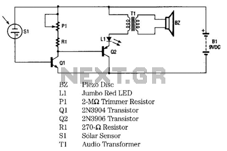
Infrared Remote-Control Tester Circuit
The infrared remote-control tester employs a sensitive PN-type solar sensor directly connected to a Darlington amplifier composed of transistors Q1 and Q2. Biasing is achieved through resistor R1 and PI, a variable resistor that functions as a sensitivity control. The...
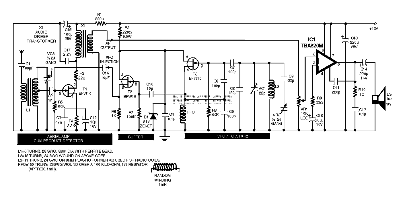
A simple remote control tester circuit diagram
This device functions as a convenient tool for testing infrared (IR) remote control transmitters used with televisions, VCRs, and similar devices. The IR signals emitted from a remote control are detected by the IR sensor module within the tester, causing...
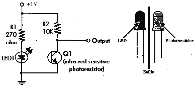
Basic IR Detector/Emitter
This is a very basic infrared detector/emitter circuit. One major downside of this circuit, is that ambient infrared light will interfere with its detecting obstacles.
The described circuit functions as a basic infrared (IR) detector and emitter system, commonly utilized in...
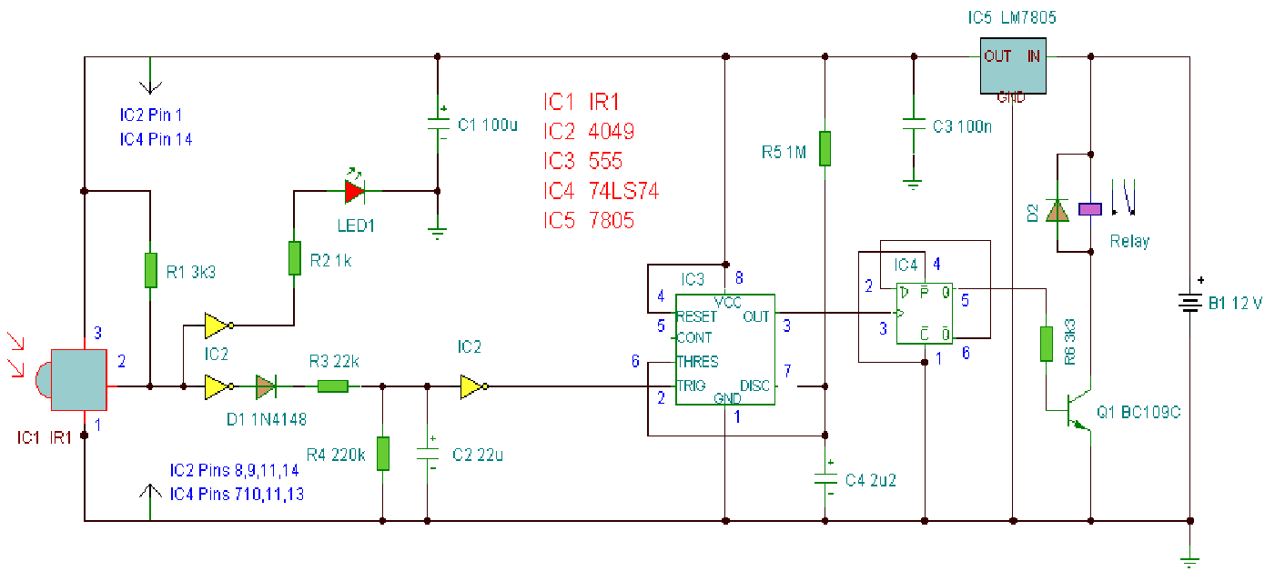
Infrared circuits related resources
A computerized infrared remote project is a simple device designed for recording and playing back streams of infrared data, specifically the codes transmitted by remote controls. Software is provided for use in both DOS and Windows environments, along with information...
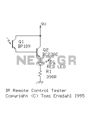
Infra-red detector circuit
This circuit is a simple IR detector for testing IR remote controllers. The circuit is based on one phototransistor which receives the IR beam. The NPN transistor works as an amplifier which feeds current to the LED. When this circuit...
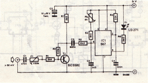
Infrared transmitter circuit schematic
This infrared transmitter utilizes pulse width modulation (PWM). The transmitter is equipped with an LM567 tone decoder circuit. An audio signal (at least 50 mV peak-to-peak) is amplified with transistor T1 and subsequently used to modulate IC1. The frequency of...
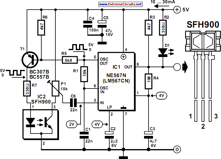
Infra-Red Proximity Detector
The detector is designed to recognize obstructions at distances ranging from a few millimeters to several centimeters. Similar devices are utilized in industrial and healthcare applications, such as activating a water tap through a magnetic valve. The sensor, IC2, is...
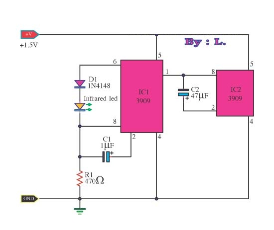
infrared transmitters using lm3909
This circuit is an infrared transmitter that operates on a low power supply of 1.5 V. The main components include two LM3909 integrated circuits, which function as an oscillator and LED flasher. Typically, this circuit is utilized as a simple...
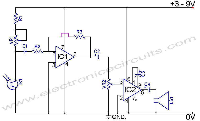
Infrared Remote Control Tester Circuit
Infrared Remote Control Tester Circuit. This is a simple circuit that can be built to test infrared remote controls. The circuit utilizes an...
This infrared remote control tester circuit is designed to verify the functionality of infrared remote controls commonly used...