


LASER Transmitter/Receiver
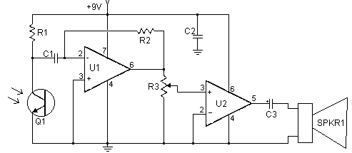
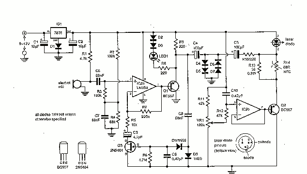
Description: This set of two circuits forms the basis for a very simple light wave transmitter. A LASER beam is modulated and then aimed at a receiver that demodulates the signal and then presents the information (voice, data, etc.). The whole thing is very easy to build and requires no specialized parts except for the LASER itself. In the transmitter schematic, no ballast resistor is shown because most small LASER power supplies already have one built in. Yours may differ, and a resistor may be needed. The receiver should be kept away from bright lights.
The circuit consists of two main components: a transmitter and a receiver. The transmitter utilizes a LASER diode, which serves as the primary light source. The modulation of the LASER beam can be achieved using a simple circuit that may include a microcontroller or an audio amplifier to encode the desired information (such as voice or data) into the light signal.
For the transmitter, a power supply is required to operate the LASER diode. While many small LASER power supplies come with an integrated ballast resistor to limit the current flowing through the LASER, it is crucial to verify the specifications of the power supply being used. If it lacks a ballast resistor, an external resistor must be added to prevent damage to the LASER diode due to excessive current.
The receiver circuit is designed to detect the modulated LASER light and convert it back into an electrical signal. This typically involves using a photodiode or a phototransistor, which is sensitive to the wavelength of the LASER light. The output from the photodetector will be a varying electrical signal corresponding to the modulation applied at the transmitter.
In order to ensure optimal performance, the receiver should be shielded from ambient light sources, particularly bright lights that could interfere with the detection of the LASER signal. This can be achieved by placing the receiver in a dark enclosure or using optical filters that only allow the specific wavelength of the LASER light to pass through.
Overall, this simple light wave transmitter and receiver circuit can effectively transmit and receive data over short distances, making it a practical solution for various applications. Careful consideration of the components and environmental factors will enhance the reliability and performance of the system.This set of two circuits from the basis for a very simple light wave transmitter. A LASER beam is modulated and then aimed at a receiver that demodulates the signal and then presents the information (voice, data, etc..). The whole thing is very easy to build and requires no specialized parts execpt for the LASER itself. In the transmitter schematic, no ballast resistor is shown because most small LASER power supplies already have one built in. Yours may differ, and a resistor may be needed. The receiver should be kept away from bright lights. You may want to put a pi
The circuit consists of two main components: a transmitter and a receiver. The transmitter utilizes a LASER diode, which serves as the primary light source. The modulation of the LASER beam can be achieved using a simple circuit that may include a microcontroller or an audio amplifier to encode the desired information (such as voice or data) into the light signal.
For the transmitter, a power supply is required to operate the LASER diode. While many small LASER power supplies come with an integrated ballast resistor to limit the current flowing through the LASER, it is crucial to verify the specifications of the power supply being used. If it lacks a ballast resistor, an external resistor must be added to prevent damage to the LASER diode due to excessive current.
The receiver circuit is designed to detect the modulated LASER light and convert it back into an electrical signal. This typically involves using a photodiode or a phototransistor, which is sensitive to the wavelength of the LASER light. The output from the photodetector will be a varying electrical signal corresponding to the modulation applied at the transmitter.
In order to ensure optimal performance, the receiver should be shielded from ambient light sources, particularly bright lights that could interfere with the detection of the LASER signal. This can be achieved by placing the receiver in a dark enclosure or using optical filters that only allow the specific wavelength of the LASER light to pass through.
Overall, this simple light wave transmitter and receiver circuit can effectively transmit and receive data over short distances, making it a practical solution for various applications. Careful consideration of the components and environmental factors will enhance the reliability and performance of the system.This set of two circuits from the basis for a very simple light wave transmitter. A LASER beam is modulated and then aimed at a receiver that demodulates the signal and then presents the information (voice, data, etc..). The whole thing is very easy to build and requires no specialized parts execpt for the LASER itself. In the transmitter schematic, no ballast resistor is shown because most small LASER power supplies already have one built in. Yours may differ, and a resistor may be needed. The receiver should be kept away from bright lights. You may want to put a pi
Advanced Laser Diagnostics Laboratory
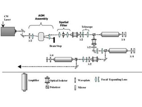
The Advanced Laser Diagnostics Laboratory (ALDL) focuses on developing and applying laser diagnostics for fluid dynamic measurements. Specialization areas include high-repetition rate flow visualization (up to 1 million frames per second) and three-dimensional imaging. The laboratory features a custom-built pulse...
Laser Trip Mine
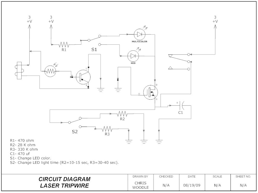
This guide will teach how to create a laser trip mine. If an individual crosses the laser's path, it has been designed to activate an LED, but you can...
To construct a laser trip mine, the circuit typically consists of a...
SW Receiver Using MK414
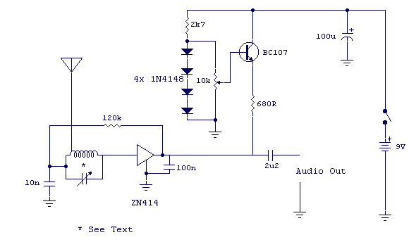
The tuned circuit consists of a variable capacitor and fixed air spaced coil. For the coil, wound between 10 and 20 turns of wire on an empty tube of around 1.5 inches diameter. The turns were spaced so that the...
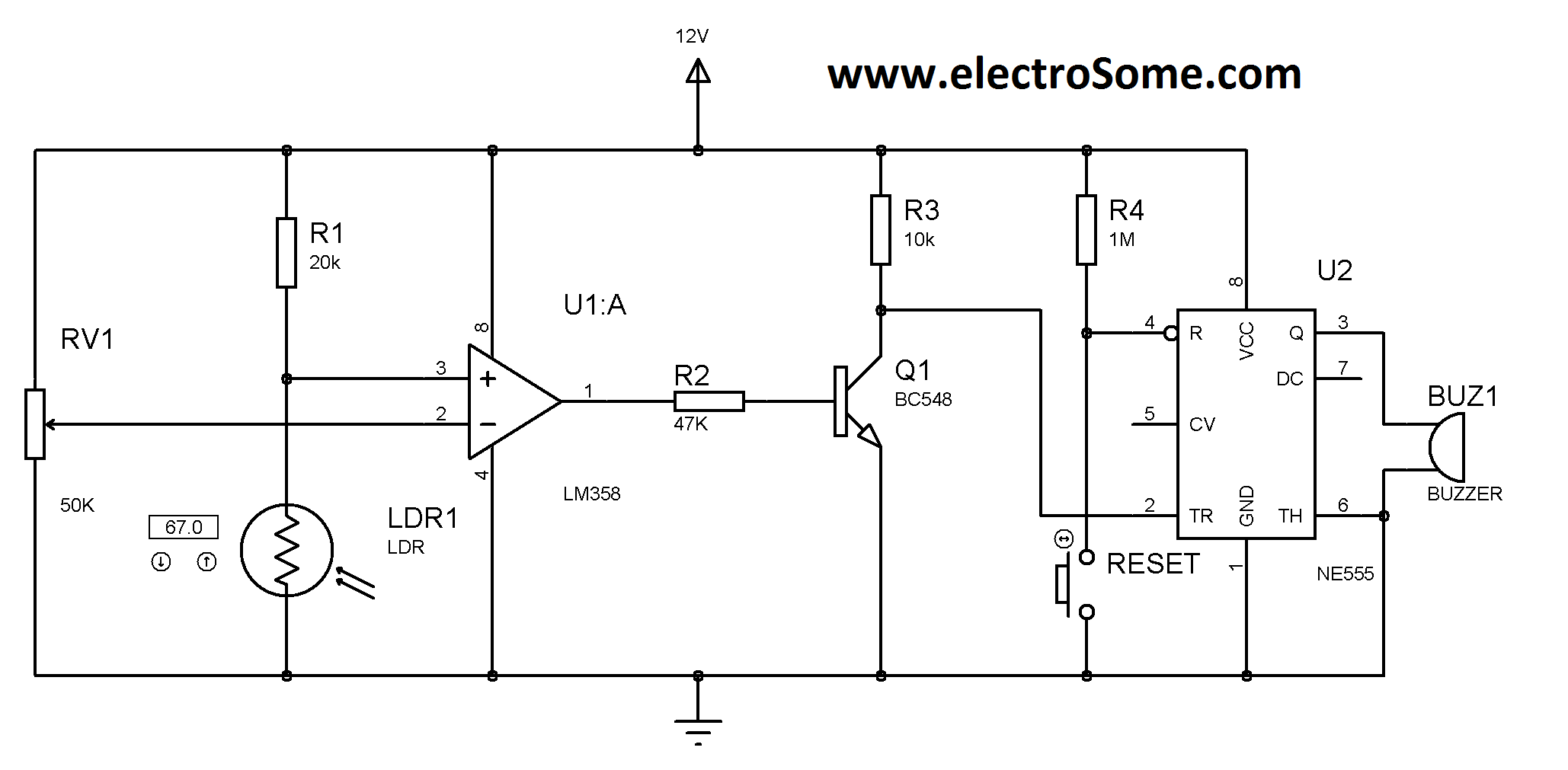
laser security system
A simple and affordable laser-based security system, costing less than Rs. 100. This circuit utilizes an LM358 operational amplifier and an LM555 timer. It is activated when the laser beam is interrupted by a light-dependent resistor (LDR), which triggers a...
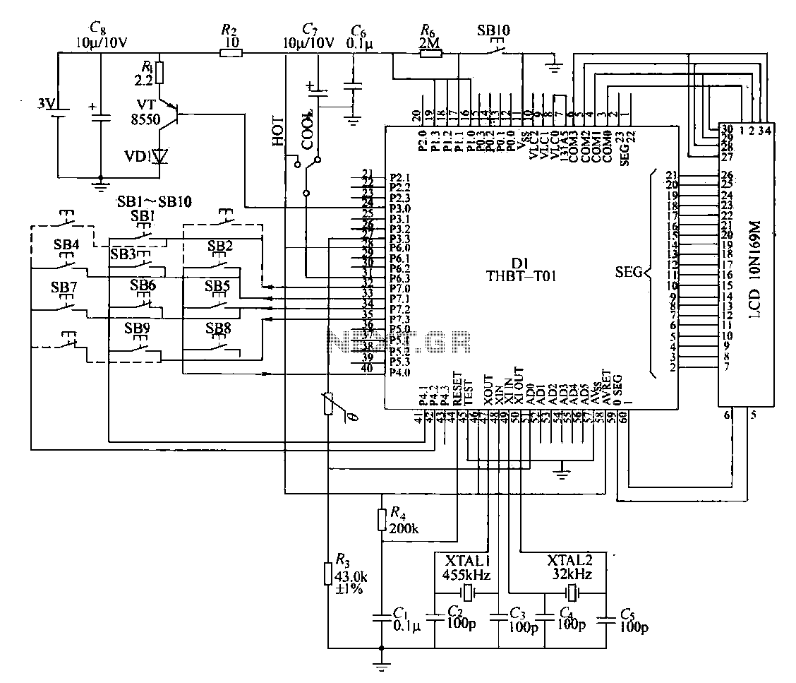
Remote control transmitter circuit
The circuit composition of a specific remote control transmitter is illustrated in a diagram. The transmitter primarily consists of a large-scale integrated circuit chip (D1, THBT-T01), a 4.5 kHz crystal oscillator, a 32 kHz crystal oscillator, a liquid crystal display...
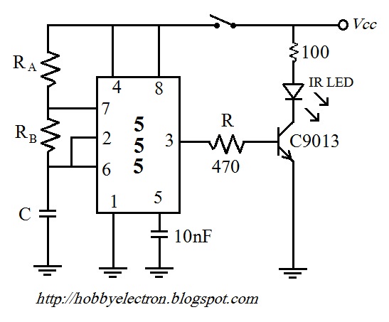
remote control circuit
The remote control circuit comprises two main components: a transmitter and a receiver. The transmitter circuit is controlled by an NE555 integrated circuit (IC), while the receiver operates based on the frequency of the signal emitted by the transmitter. It...
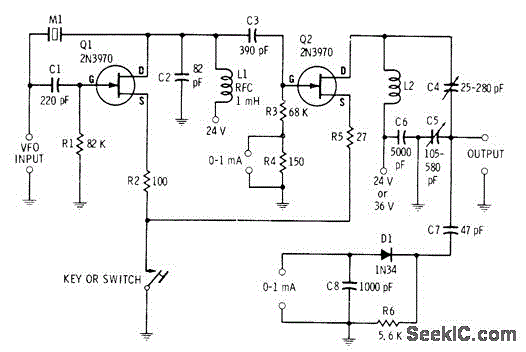
14W CW TRANSMITTER
A low-power two-stage FET transmitter designed for the 80-meter amateur band utilizes a Pierce crystal oscillator that does not require an output resonant circuit. A DC milliammeter can be connected across a 150-ohm resistor in the gate circuit of the...

Laser Alarm
This circuit is a laser alarm system similar to those depicted in various movies. It employs a laser pointer beam to secure valuables and property. When the beam is interrupted by a person, animal, or object, the resistance of a...
LASER LINK COMMUNICATOR
As before, there are two sections: the transmitter board and the receiver board, both powered by a separate 9V battery or a fixed voltage power supply, depending on your needs. The transmitter board has an electret microphone module at one...