


learning How does this SIM card reader circuit work
#SIM card reader
#CMOS hex inverter
#serial communication
#PC interface
#electronic hobby
#simple circuit
#communication protocol
#data reading
#DIY electronics
#learning circuits
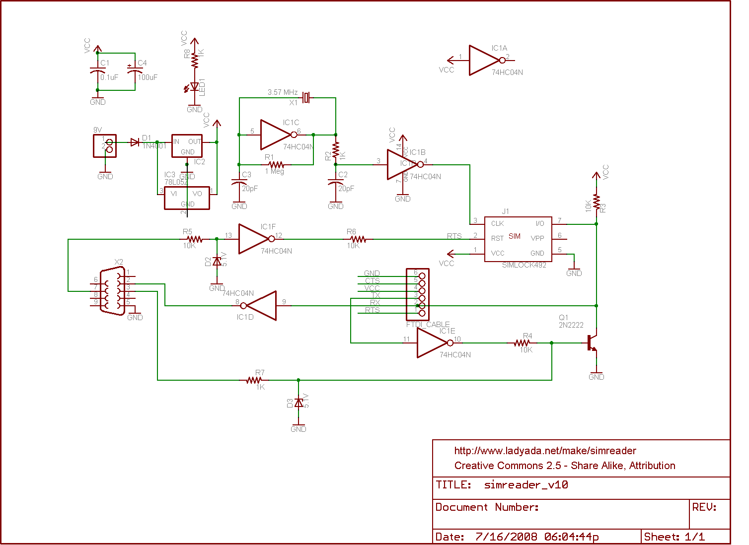
Description: The circuit for a SIM card reader is presented here. It utilizes a CMOS hex inverter along with other basic components. Not only does it function effectively, but it is also capable of communicating with a PC through a serial port. The simplicity of this design can be surprising for those new to electronic circuits. It is suggested that a microcontroller may be used in conjunction with this circuit. Furthermore, it is important to verify any links provided, as formatting errors can lead to broken connections. Additionally, it should be noted that the signal levels emitted from the DB9 header are not compliant with RS232 standards, which typically require signal levels of at least +/- 9V, whereas this circuit outputs 0.5V, which is classified as TTL.
The SIM card reader circuit is designed to interface with SIM cards and enable communication with a PC. The core component of this circuit is the CMOS hex inverter, which is used to convert the logic levels of the signals from the SIM card to levels that can be understood by the PC. The circuit may include additional passive components such as resistors and capacitors to stabilize the signal and filter noise, ensuring reliable communication.
The circuit can be powered by a standard power supply, which should be compatible with the voltage requirements of the CMOS components. The connection to the PC is typically made through a DB9 serial port, which allows for straightforward data transmission. However, it is crucial to note that the voltage levels outputted through the DB9 connector are TTL levels, which are not suitable for direct RS232 communication. To achieve RS232 compatibility, a level shifter or RS232 driver may be required to convert the TTL signal levels to the appropriate voltages.
When designing or assembling this circuit, careful attention should be paid to the layout and connections to prevent any signal integrity issues. Proper grounding and decoupling techniques should be employed to minimize interference and ensure stable operation. As this circuit is aimed at hobbyists and beginners, clear documentation and schematic diagrams should accompany the design to facilitate understanding and implementation.
Overall, this SIM card reader circuit serves as an excellent introduction to electronic design and interfacing, providing valuable hands-on experience in working with digital signals and communication protocols.The circuit for a SIM card reader is shown here. The circuit uses a CMOS hex inverter and other simple components; yet, not only does it work but it can also communicate with a PC via serial port! I am learning electronic circuits as a hobby and I was baffled to see how simple this was. I was thinking of using some kind of micro controller for th is. As you can see I am a complete amateur. Olin wanted you to learn by doing - and it is often the best way to learn. I wanted to use the link as intened so fixed it BUT you should always check your links after positing to make sure they are OK. The problem was small but fatal. Links are of form [label stuff](URL) with no gaps between ] and (. You had a space between ] and ( so it didn`t work. Russell McMahon Dec 29 `11 at 13:55 Please note that the signal levels going out on the DB9 header are not RS232 compliant.
RS232 should be (I believe) +/- 9V atleast, and this only does 0. 5V (known as TTL) Hans Dec 29 `11 at 20:48
The SIM card reader circuit is designed to interface with SIM cards and enable communication with a PC. The core component of this circuit is the CMOS hex inverter, which is used to convert the logic levels of the signals from the SIM card to levels that can be understood by the PC. The circuit may include additional passive components such as resistors and capacitors to stabilize the signal and filter noise, ensuring reliable communication.
The circuit can be powered by a standard power supply, which should be compatible with the voltage requirements of the CMOS components. The connection to the PC is typically made through a DB9 serial port, which allows for straightforward data transmission. However, it is crucial to note that the voltage levels outputted through the DB9 connector are TTL levels, which are not suitable for direct RS232 communication. To achieve RS232 compatibility, a level shifter or RS232 driver may be required to convert the TTL signal levels to the appropriate voltages.
When designing or assembling this circuit, careful attention should be paid to the layout and connections to prevent any signal integrity issues. Proper grounding and decoupling techniques should be employed to minimize interference and ensure stable operation. As this circuit is aimed at hobbyists and beginners, clear documentation and schematic diagrams should accompany the design to facilitate understanding and implementation.
Overall, this SIM card reader circuit serves as an excellent introduction to electronic design and interfacing, providing valuable hands-on experience in working with digital signals and communication protocols.The circuit for a SIM card reader is shown here. The circuit uses a CMOS hex inverter and other simple components; yet, not only does it work but it can also communicate with a PC via serial port! I am learning electronic circuits as a hobby and I was baffled to see how simple this was. I was thinking of using some kind of micro controller for th is. As you can see I am a complete amateur. Olin wanted you to learn by doing - and it is often the best way to learn. I wanted to use the link as intened so fixed it BUT you should always check your links after positing to make sure they are OK. The problem was small but fatal. Links are of form [label stuff](URL) with no gaps between ] and (. You had a space between ] and ( so it didn`t work. Russell McMahon Dec 29 `11 at 13:55 Please note that the signal levels going out on the DB9 header are not RS232 compliant.
RS232 should be (I believe) +/- 9V atleast, and this only does 0. 5V (known as TTL) Hans Dec 29 `11 at 20:48
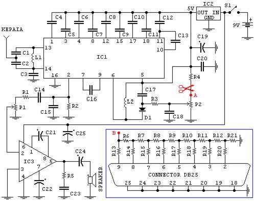
PC FM Radio Circuit
If familiar with programming languages such as C++, PASCAL, VISUAL BASIC, or DELPHI, it is possible to write a program that sends numbers from 0 to 255 through the parallel port (378 I) of a PC. This process checks the...
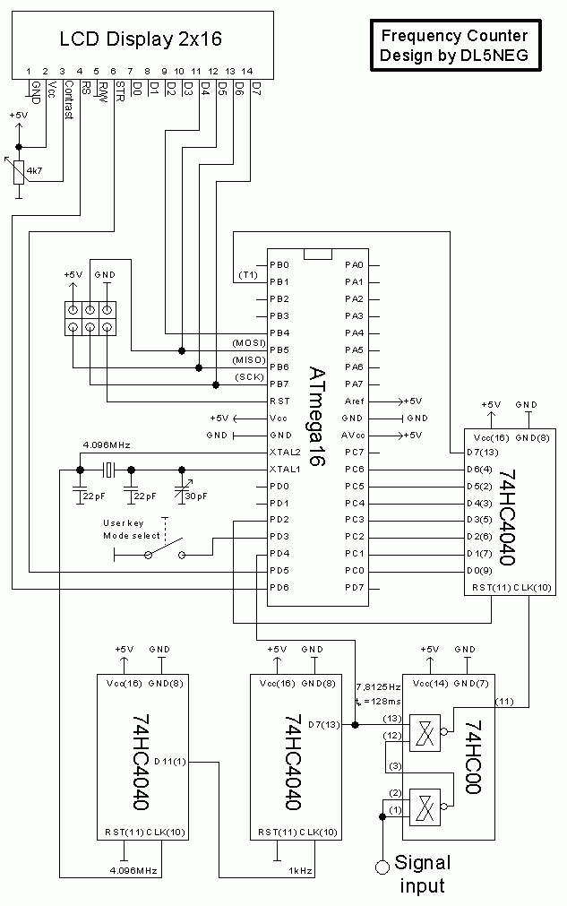
universal serial PC interface
Every hobbyist eventually considers ideas for controlling or measuring something with a PC. The allure of this concept is strong, especially with the abundance of easy-to-learn programming languages available today, enabling almost anyone to write software for tasks such as...
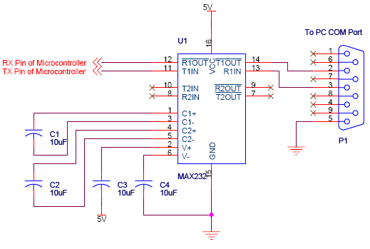
serial communication introduction
Serial communication using UART or USART of a microcontroller 8051 AVR PIC, software implementation of half-duplex UART and MAX232 interfacing with microcontrollers 8051 AVR PIC.
The described system focuses on implementing serial communication via UART (Universal Asynchronous Receiver-Transmitter) or USART (Universal...

pc frs radio control
Tutorials, reviews, and software regarding airsoft. This project illustrates how to connect a PC to a small FRS radio via a simple RS-232 interface. There are several reasons for this connection.
This project focuses on establishing a communication link between a...
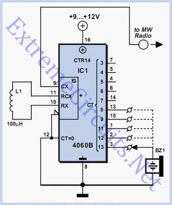
Simple Oscillator / Pipe Locator
Occasionally, there is a requirement to create a very basic oscillator. The circuit illustrated here is remarkably straightforward, utilizing only three components.
The described oscillator circuit typically consists of a resistor, a capacitor, and a single transistor. The operation of this...
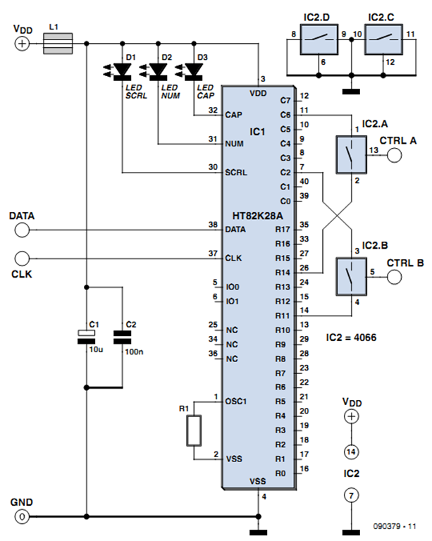
control interface via pc keyboard
One of the more challenging aspects of creating a control or security system that utilizes a PC, such as a burglar alarm, is connecting the sensors to the computer. This typically requires specialized interface expansion boards, and programming that includes...
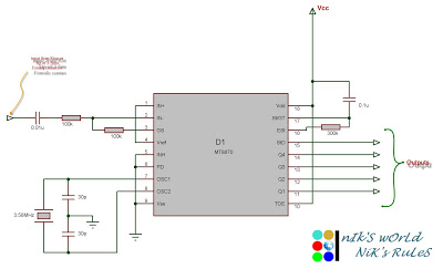
Microcontroller circuits
Connect the serial cable to the serial port. If using a USB to TTL, RS232, or serial converter, plug it into the USB port. Next, short the Tx pin to the Rx pin or the TxD pin to the RxD...
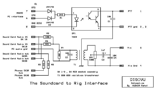
Build your own PC interface
TNCs and modems dominated the field of digital communications until recently. With the introduction of high-speed computing and digital signal processing (DSP), this landscape has changed. If an individual possesses a home computer (PC) equipped with a sound card, they...