


Low-power-rs-232c-driver
#RS-232C
#low-power
#driver
#communication
#voltage converter
#5V supply
#short-circuit protection
#serial communication
#data transmission
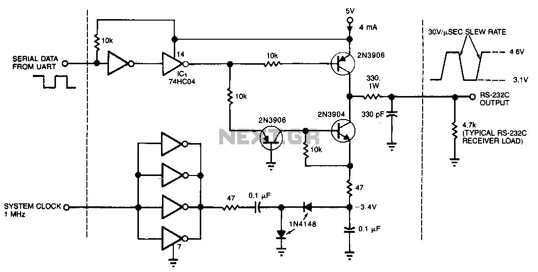
Description: This circuit draws only 4 mA from a 5-V supply while driving a standard RS-232C receiver. The system clock drives a de-de converter that produces -3.4 V. The frequency can range from 0.5 to 8 MHz, but a range of 0.5 to 1 MHz will minimize power dissipation. The circuit output withstands direct shorts to ground or to either of the supplies (±12 V max). In place of the 74HC04 high-speed CMOS driver shown, one may want to substitute miscellaneous spare gates; one non-inverting buffer, for example, can replace the two inverting types that receive the UART signal.
The described circuit is designed to interface with an RS-232C receiver while maintaining low power consumption, drawing only 4 mA from a 5-V supply. The core of the circuit involves a system clock that drives a de-de converter, which generates a negative voltage of -3.4 V essential for RS-232 communication. The operational frequency of the circuit is flexible, ranging from 0.5 MHz to 8 MHz; however, operation within the 0.5 MHz to 1 MHz range is recommended to achieve optimal power efficiency and minimize heat generation.
The circuit's output is robust, capable of enduring direct shorts to ground or to either of the supply voltages, which can reach up to ±12 V. This feature enhances the reliability of the circuit in various applications, ensuring that accidental shorts do not lead to circuit failure.
For flexibility in component selection, the design allows for the substitution of the 74HC04 high-speed CMOS driver with other available logic gates. Specifically, a single non-inverting buffer can effectively replace two inverting buffers that typically process the UART signal. This adaptability not only facilitates component sourcing but also allows for design modifications based on available parts without compromising circuit functionality. The careful selection of components and operating parameters ensures that the circuit remains efficient and reliable in its intended applications.This circuit draws only 4 mA from a 5-V supply while driving a standard RS-232C receiver. The system clock drives a de-de converter that produces -3.4 V. The frequency can range from 0.5 to 8 MHz, but a range of 0.5 to 1 MHz will minimize power dissipation. The circuit output withstands direct shorts to ground or to either of the supplies ( ±12 V max). In place of the 74HC04 high-speed CMOS driver shown, you may want to substitute miscellaneous spare gates; one noninverting buffer, for example, can replace the two inverting types that receive the UART signal.
The described circuit is designed to interface with an RS-232C receiver while maintaining low power consumption, drawing only 4 mA from a 5-V supply. The core of the circuit involves a system clock that drives a de-de converter, which generates a negative voltage of -3.4 V essential for RS-232 communication. The operational frequency of the circuit is flexible, ranging from 0.5 MHz to 8 MHz; however, operation within the 0.5 MHz to 1 MHz range is recommended to achieve optimal power efficiency and minimize heat generation.
The circuit's output is robust, capable of enduring direct shorts to ground or to either of the supply voltages, which can reach up to ±12 V. This feature enhances the reliability of the circuit in various applications, ensuring that accidental shorts do not lead to circuit failure.
For flexibility in component selection, the design allows for the substitution of the 74HC04 high-speed CMOS driver with other available logic gates. Specifically, a single non-inverting buffer can effectively replace two inverting buffers that typically process the UART signal. This adaptability not only facilitates component sourcing but also allows for design modifications based on available parts without compromising circuit functionality. The careful selection of components and operating parameters ensures that the circuit remains efficient and reliable in its intended applications.This circuit draws only 4 mA from a 5-V supply while driving a standard RS-232C receiver. The system clock drives a de-de converter that produces -3.4 V. The frequency can range from 0.5 to 8 MHz, but a range of 0.5 to 1 MHz will minimize power dissipation. The circuit output withstands direct shorts to ground or to either of the supplies ( ±12 V max). In place of the 74HC04 high-speed CMOS driver shown, you may want to substitute miscellaneous spare gates; one noninverting buffer, for example, can replace the two inverting types that receive the UART signal.
Rs232c-led-circuit
Utilize a pair of Maxim's 5V-powered MAX231 RS-232C transmitters as drivers to achieve a dual-color LED. These transmitters necessitate only a single-ended, 5-V input to internally generate ±10 V. Their outputs are designed to be short-circuit-proof and can provide up...
240 110V voltage converter circuit diagram
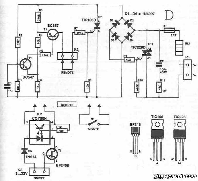
This circuit diagram illustrates the design of a straightforward AC voltage converter that transforms 240V AC power into 110V AC. The circuit can effectively be utilized to power electrical devices that necessitate a supply voltage of 110V.
The AC voltage converter...
Inductorless 5V to -5V Converter
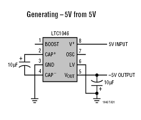
The LTC1046 is a 50mA monolithic CMOS switched capacitor voltage converter. It serves as a replacement for the ICL7660/LTC1044 in 5V applications where higher output current is required. This device is optimized for high current capability with input voltages of...
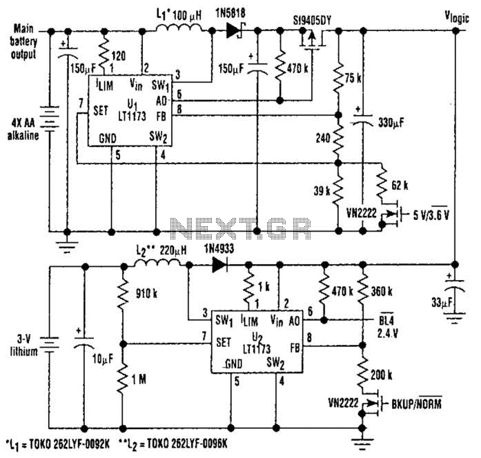
5V From 4Aa Cells Circuit
This unique logic-power-converter design allows for a switchable output of 3.6 V or 5 V at 200 mA using four AA cells. The supply features a MOSFET switch that can connect to a lithium backup battery, providing a 3.4 V...
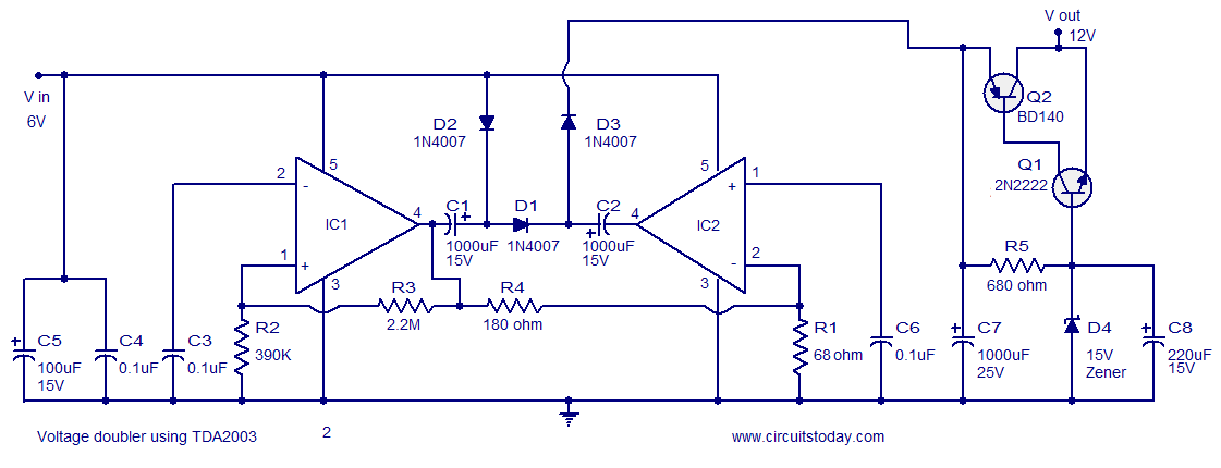
Voltage Converter 6 to 12 Volts -Using TDA 2003
A reliable voltage converter circuit that operates between 6 to 12 volts, utilizing the audio amplifier IC TDA 2003. This voltage doubler circuit can be assembled on a Vero board.
The voltage converter circuit designed with the TDA 2003 audio amplifier...
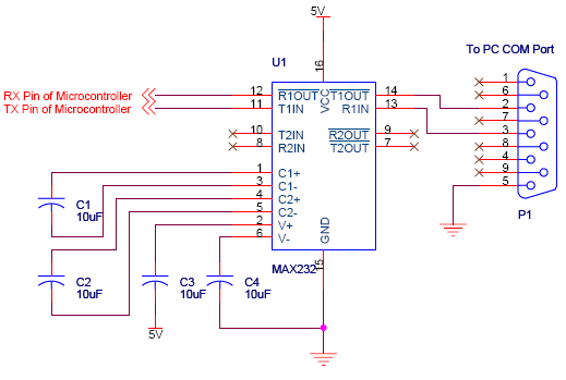
serial communication introduction
Serial communication using UART or USART of a microcontroller 8051 AVR PIC, software implementation of half-duplex UART and MAX232 interfacing with microcontrollers 8051 AVR PIC.
The described system focuses on implementing serial communication via UART (Universal Asynchronous Receiver-Transmitter) or USART (Universal...
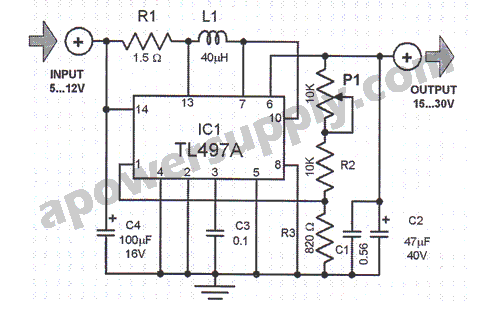
TL497A Voltage Converter
This voltage converter is constructed using the TL497A integrated circuit and is designed to convert an input voltage range of 5 to 12 volts into a higher output voltage range of 15 to 30 volts. This functionality is particularly beneficial...
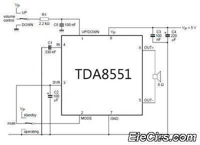
Low-Power Amplifier with digital volume control
An amplifier with digital volume control can be designed predictably due to the simplicity of the circuit, which utilizes a single chip, the TDA8551. This series of mini amplifiers with digital volume control operates as a BTL (Bridge-Tied Load) amplifier...
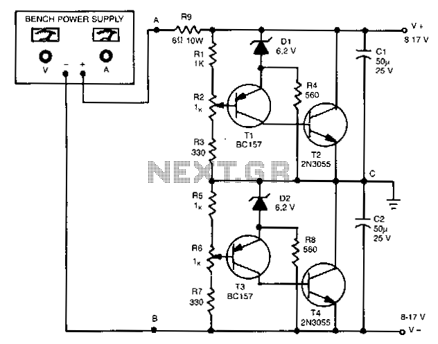
Unipolar-to-dual-supply-converter
The outputs in this circuit are independently variable and can be loaded unsymmetrically. The output voltage remains constant, regardless of load and changes. By varying potentiometers R2 or R6, the output voltages can be conveniently set. Outputs can be adjusted...