


MIDI to Sync24 Convertor
#MIDI
#Sync24
#clock converter
#DIN sync
#Roland
#start/stop signal
#music gear
#electronic music
#pulse generator
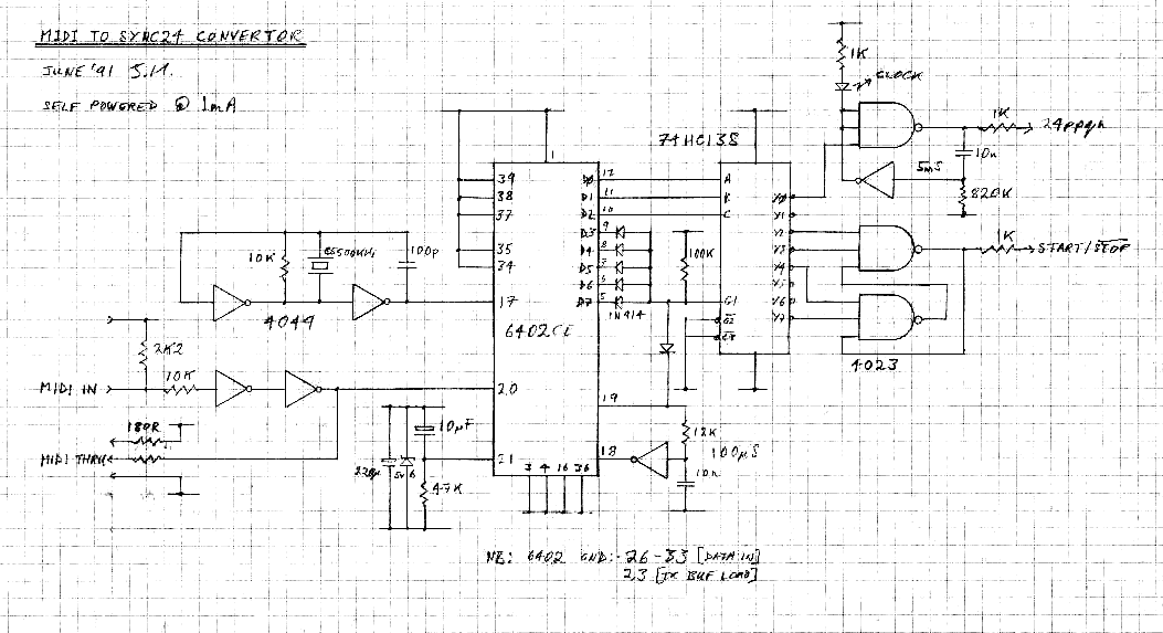
Description: This self-powered circuit converts MIDI clocks to DIN sync24. This type of clock is used on old Roland gear and provides a 24 pulses per quarter note clock and a start/stop signal.
The circuit functions by receiving MIDI clock signals, which are digital pulses sent at a specific rate to synchronize electronic musical instruments. The MIDI clock operates at a frequency of 24 pulses per quarter note, which is essential for maintaining tempo across devices. The self-powered nature of the circuit allows it to operate independently without requiring an external power source, making it particularly suitable for mobile setups or environments where power availability is limited.
The conversion process involves the detection of MIDI clock signals, which are typically transmitted via a 5-pin DIN connector. The circuit includes a microcontroller or dedicated integrated circuit that interprets these MIDI signals. Upon receiving a MIDI clock signal, the circuit generates a corresponding DIN sync24 output. This output consists of 24 square wave pulses for each quarter note, effectively translating the MIDI clock into a format compatible with older Roland gear and other devices that utilize DIN sync.
Additionally, the circuit incorporates a start/stop signal feature. This is crucial for synchronizing playback or recording between devices. When the MIDI clock starts, a designated signal is sent to indicate the start of playback, while a separate signal is triggered to denote the stop condition. This ensures that all connected devices remain in sync, allowing for cohesive performance across multiple instruments.
Overall, this self-powered circuit serves as a vital link between modern MIDI technology and vintage equipment, facilitating the integration of various musical devices and enhancing the versatility of electronic music setups.This self-powered circuit converts MIDI clocks to DIN sync24. This type of clock is used on old Roland gear and provides a 24 pulses per quarter note clock and a start/stop signal.
The circuit functions by receiving MIDI clock signals, which are digital pulses sent at a specific rate to synchronize electronic musical instruments. The MIDI clock operates at a frequency of 24 pulses per quarter note, which is essential for maintaining tempo across devices. The self-powered nature of the circuit allows it to operate independently without requiring an external power source, making it particularly suitable for mobile setups or environments where power availability is limited.
The conversion process involves the detection of MIDI clock signals, which are typically transmitted via a 5-pin DIN connector. The circuit includes a microcontroller or dedicated integrated circuit that interprets these MIDI signals. Upon receiving a MIDI clock signal, the circuit generates a corresponding DIN sync24 output. This output consists of 24 square wave pulses for each quarter note, effectively translating the MIDI clock into a format compatible with older Roland gear and other devices that utilize DIN sync.
Additionally, the circuit incorporates a start/stop signal feature. This is crucial for synchronizing playback or recording between devices. When the MIDI clock starts, a designated signal is sent to indicate the start of playback, while a separate signal is triggered to denote the stop condition. This ensures that all connected devices remain in sync, allowing for cohesive performance across multiple instruments.
Overall, this self-powered circuit serves as a vital link between modern MIDI technology and vintage equipment, facilitating the integration of various musical devices and enhancing the versatility of electronic music setups.This self-powered circuit converts MIDI clocks to DIN sync24. This type of clock is used on old Roland gear and provides a 24 pulses per quarter note clock and a start/stop signal.
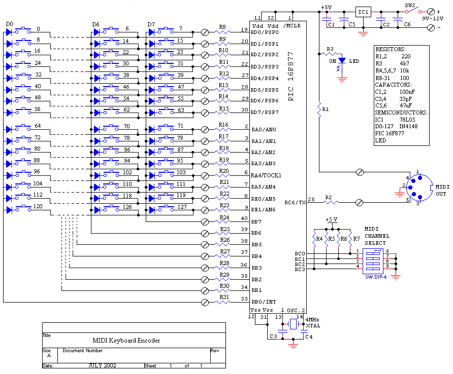
MID Bass Pedal
The MIDI Bass Pedal utilizes a MIDI keyboard encoder (MKE) that can encode a variable number of momentary action, push-to-make, single pole single throw (SPST) switches, ranging from 1 to 128, to generate corresponding MIDI note-on/note-off data commands. The encoded...
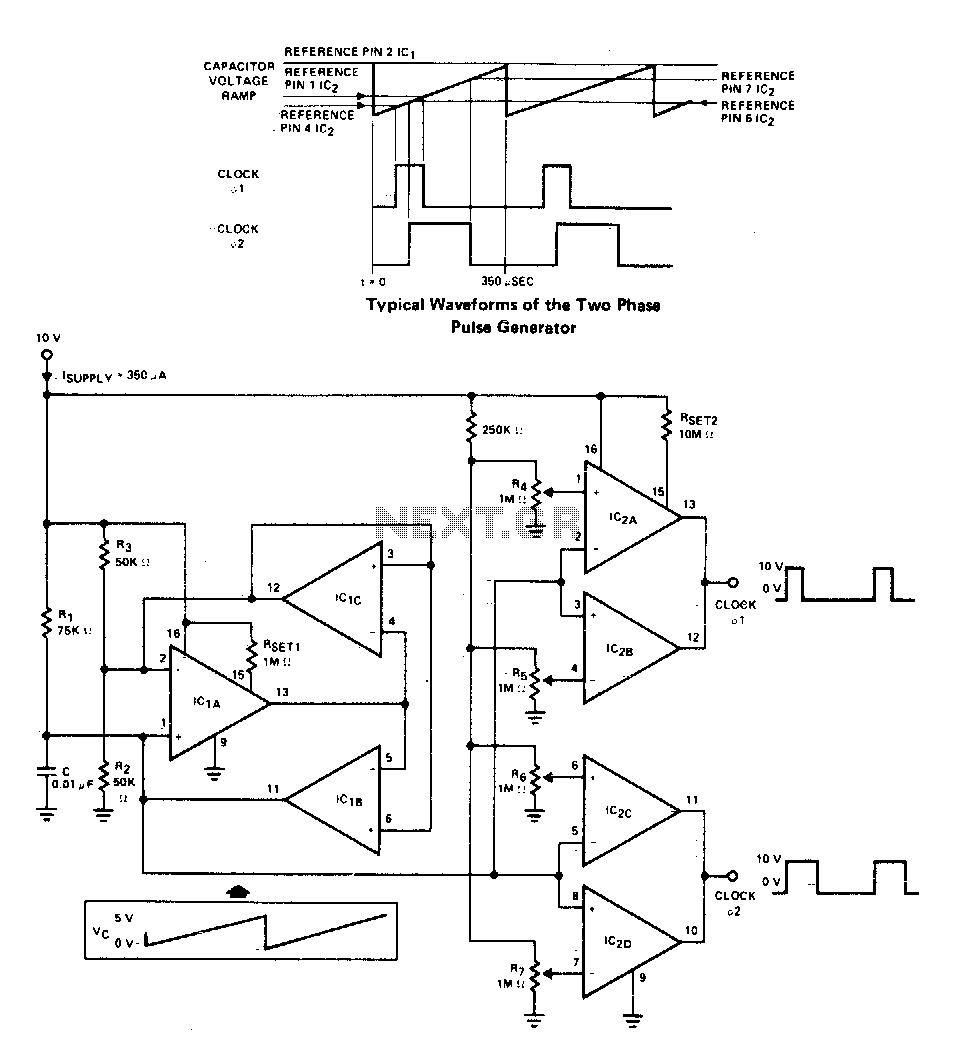
Versatile two-phase pulse generator
A two-phase clock generator utilizes two L161 integrated circuits to produce pulses with adjustable widths and phase relationships. Additionally, a ramp generator supplies input to two variable window comparators, which are configured using IC2A-IC2B and IC2C-IC2D, respectively.
The two-phase clock generator...
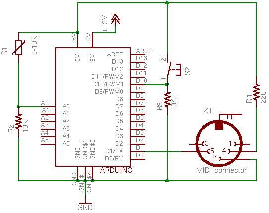
MIDI Output with Arduino
This page covers only the details of MIDI communication on the Arduino module. For a more general introduction to MIDI on a microprocessor, see the MIDI notes on Tom's physical computing site. MIDI, the Musical Instrument Digital Interface, is a...
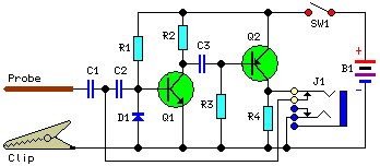
Pulse Generator And Signal TracerCircuit
This simple circuit generates narrow pulses at a frequency of approximately 700-800 Hz. The pulses, which contain harmonics extending into the MHz range, can be injected into audio or radio-frequency stages of amplifiers and receivers for testing purposes. A high-pitched...
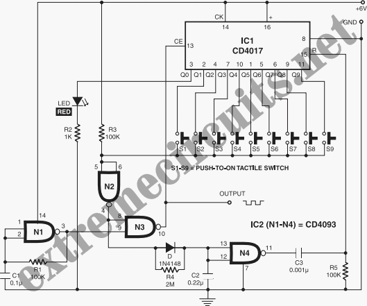
Pulse Generator
This circuit is quite effective for testing or operating counters and stepping relays, as it eliminates the need for manually setting a switch for the desired number of pulses. By pressing the appropriate switches S1 to S9, one can generate...
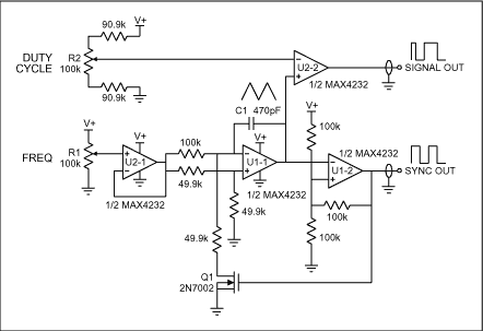
Simple Pulse Generator
A pulse generator typically allows control over the pulse repetition rate, pulse width, pulse delay, and pulse amplitude. More advanced pulse generators may also enable adjustments to the rise time and fall time of the pulses. The delay of a...
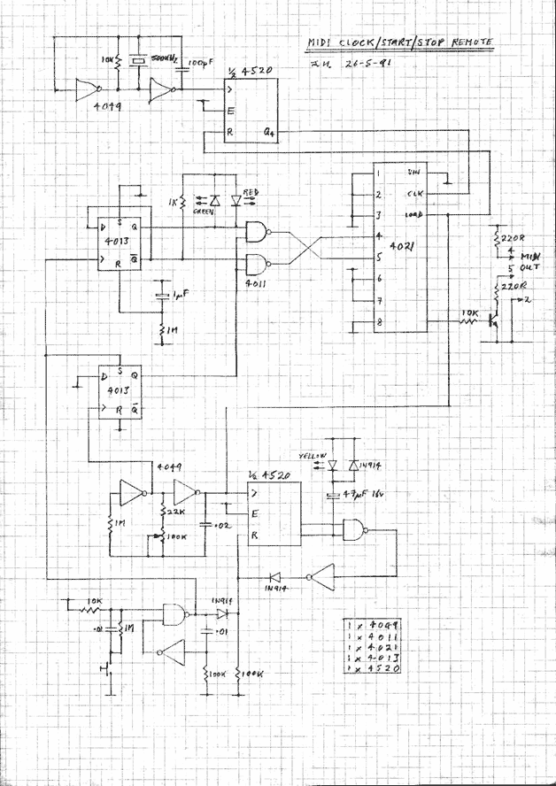
MIDI Clock
This circuit generates MIDI clocks and start/stop messages.
The described circuit is designed to produce MIDI clock signals and control messages, which are essential for synchronizing musical devices that utilize the MIDI (Musical Instrument Digital Interface) protocol. The primary function of...
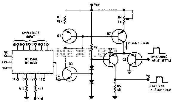
Programmable pulse generator
Fast rise and fall times necessitate the utilization of high-speed switching transistors for the differential pair, Q4 and Q5. Linear ramps and sine waves can be produced using the suitable reference input.
The circuit employs high-speed switching transistors, specifically Q4 and...
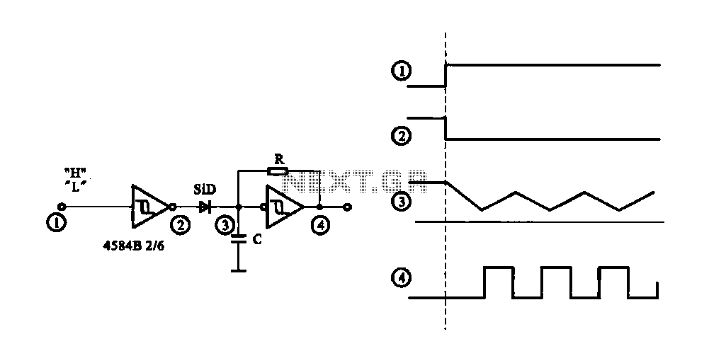
Controlled pulse signal generating circuit
The circuit generates a controlled pulse signal. When a high pulse signal is applied to the input terminal O (start), the output pulse signal is activated. Conversely, when a low signal is received at the input terminal O (stop), the...