


Nikon CLS Slave Flash Trigger
#Nikon CLS
#flash trigger
#slave flash
#photography
#camera flashes
#IR communication
#light sensing
#timing circuit
#pre-flash detection
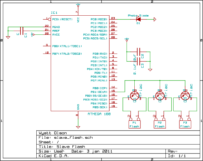
Description: This project involves a slave flash capable of triggering up to four camera flashes in non-TTL mode. It is designed for use with the Nikon CLS system but may also function with other brands that share similar protocol heuristics. The Nikon CLS system operates through a series of short pre-flashes followed by a delay and then the main flash. The implemented algorithm detects these flashes, counts any that occur within a specified time frame, and activates the slave flashes when another flash occurs within designated minimum and maximum intervals. Resources from the Digital Photography Tips and Technique blog, including an article on Nikon CLS Advanced Wireless Lighting and an Arduino-based slave flash implementation, were utilized for protocol understanding. However, a plain AVR microcontroller was chosen for this project instead of an Arduino. The schematic is straightforward, utilizing an AVR microcontroller (currently an ATmega168, although it should be compatible with most modern AVRs with adequate memory), a status LED, a photodiode operating in photovoltaic mode, and several triacs for triggering the flashes. The code incorporates define statements for threshold constants and port/pin definitions, along with custom libraries for analog readings and time counting. The entire assembly is housed in a compact enclosure built on a breadboard, allowing for modifications while maintaining a professional appearance. A power plug and regulator are included for wall power, with plans to add a small battery for portability. The LED and photodiode are positioned on the front, while flash connections are located on the back, utilizing RCA connectors for modified flashes with RCA sync inputs.
This project is an innovative solution for photographers seeking to enhance their lighting setup with multiple slave flashes. The slave flash system is particularly useful in scenarios requiring off-camera lighting, providing greater flexibility in flash placement and creative lighting effects. The use of an AVR microcontroller, such as the ATmega168, allows for efficient processing of the flash timing and control algorithms, ensuring reliable operation in various shooting conditions.
The implementation of the photodiode in photovoltaic mode is critical for accurately detecting incoming flashes, as it converts light into an electrical signal that the microcontroller can process. The choice of triacs for triggering the flashes provides robust performance, allowing for the control of high-voltage flash units without the need for complex relay circuits. The simple yet effective design ensures that the system can be easily assembled and modified, making it an excellent option for hobbyists and professionals alike.
The enclosure design, combining a breadboard with a professional housing, emphasizes both functionality and aesthetics. This approach not only protects the electronic components but also allows for quick adjustments and troubleshooting. The inclusion of a power regulator and the option for battery operation enhances the versatility of the system, enabling use in various environments, whether in a studio or on location.
Overall, this slave flash project exemplifies a practical application of microcontroller technology in photography, providing a cost-effective method to expand lighting capabilities and achieve more dynamic results in photographic compositions.This small project is a slave flash, which can trigger up to 4 camera flashes (non-TTL mode). It is meant for use with the Nikon CLS system, although it can probably work with other brands as well, as long as the protocol heuristics are similar. The heuristics of the Nikon CLS system are simple: there are a number of short pre-flashes, then a dela
y, then the main flash. The algorithm I am using basically waits until it sees a flash, reads in any number of flashes which occur with less than the designated time between them, and when another flash happens which is between the specified min and max times, it fires the slave flashes. The Digital Photography Tips and Technique blog wrote an article on Nikon CLS Advanced Wireless Lighting, as well as an implementation of a slave flash using the Arduino.
I used these resources heavily for understanding the protocol, although I chose to use a plain AVR instead of an Arduino for this project. The schematics are simple. I use an AVR (I am currently using an ATmega168, but in theory this should be portable to most modern AVRs with sufficient memory), with a status LED, photo diode (used in photo voltaic mode), and a few triacs for the actual trigger: The code is very simple.
I use define statements for all threshold constants and port / pin definitions. I use my own libraries for the analog readings and the time counting; I plan to release these eventually, but they are not yet on my website; please feel free to email me with questions or if you would like me to send them to you. I put the entire thing into a small enclosure, on a breadboard (I love breadboards within enclosures - it gives the professional look of a real enclosure, with the ability to change things that is inherent with breadboards!) There is a power plug and regulator in case I want to plug it into the wall; I also plan on including a small battery to power it eventually.
The LED and photo diode on are on the front, while the flash connections are on the back (I use RCA connectors for this, along with modified flashes with RCA sync inputs).
This project is an innovative solution for photographers seeking to enhance their lighting setup with multiple slave flashes. The slave flash system is particularly useful in scenarios requiring off-camera lighting, providing greater flexibility in flash placement and creative lighting effects. The use of an AVR microcontroller, such as the ATmega168, allows for efficient processing of the flash timing and control algorithms, ensuring reliable operation in various shooting conditions.
The implementation of the photodiode in photovoltaic mode is critical for accurately detecting incoming flashes, as it converts light into an electrical signal that the microcontroller can process. The choice of triacs for triggering the flashes provides robust performance, allowing for the control of high-voltage flash units without the need for complex relay circuits. The simple yet effective design ensures that the system can be easily assembled and modified, making it an excellent option for hobbyists and professionals alike.
The enclosure design, combining a breadboard with a professional housing, emphasizes both functionality and aesthetics. This approach not only protects the electronic components but also allows for quick adjustments and troubleshooting. The inclusion of a power regulator and the option for battery operation enhances the versatility of the system, enabling use in various environments, whether in a studio or on location.
Overall, this slave flash project exemplifies a practical application of microcontroller technology in photography, providing a cost-effective method to expand lighting capabilities and achieve more dynamic results in photographic compositions.This small project is a slave flash, which can trigger up to 4 camera flashes (non-TTL mode). It is meant for use with the Nikon CLS system, although it can probably work with other brands as well, as long as the protocol heuristics are similar. The heuristics of the Nikon CLS system are simple: there are a number of short pre-flashes, then a dela
y, then the main flash. The algorithm I am using basically waits until it sees a flash, reads in any number of flashes which occur with less than the designated time between them, and when another flash happens which is between the specified min and max times, it fires the slave flashes. The Digital Photography Tips and Technique blog wrote an article on Nikon CLS Advanced Wireless Lighting, as well as an implementation of a slave flash using the Arduino.
I used these resources heavily for understanding the protocol, although I chose to use a plain AVR instead of an Arduino for this project. The schematics are simple. I use an AVR (I am currently using an ATmega168, but in theory this should be portable to most modern AVRs with sufficient memory), with a status LED, photo diode (used in photo voltaic mode), and a few triacs for the actual trigger: The code is very simple.
I use define statements for all threshold constants and port / pin definitions. I use my own libraries for the analog readings and the time counting; I plan to release these eventually, but they are not yet on my website; please feel free to email me with questions or if you would like me to send them to you. I put the entire thing into a small enclosure, on a breadboard (I love breadboards within enclosures - it gives the professional look of a real enclosure, with the ability to change things that is inherent with breadboards!) There is a power plug and regulator in case I want to plug it into the wall; I also plan on including a small battery to power it eventually.
The LED and photo diode on are on the front, while the flash connections are on the back (I use RCA connectors for this, along with modified flashes with RCA sync inputs).
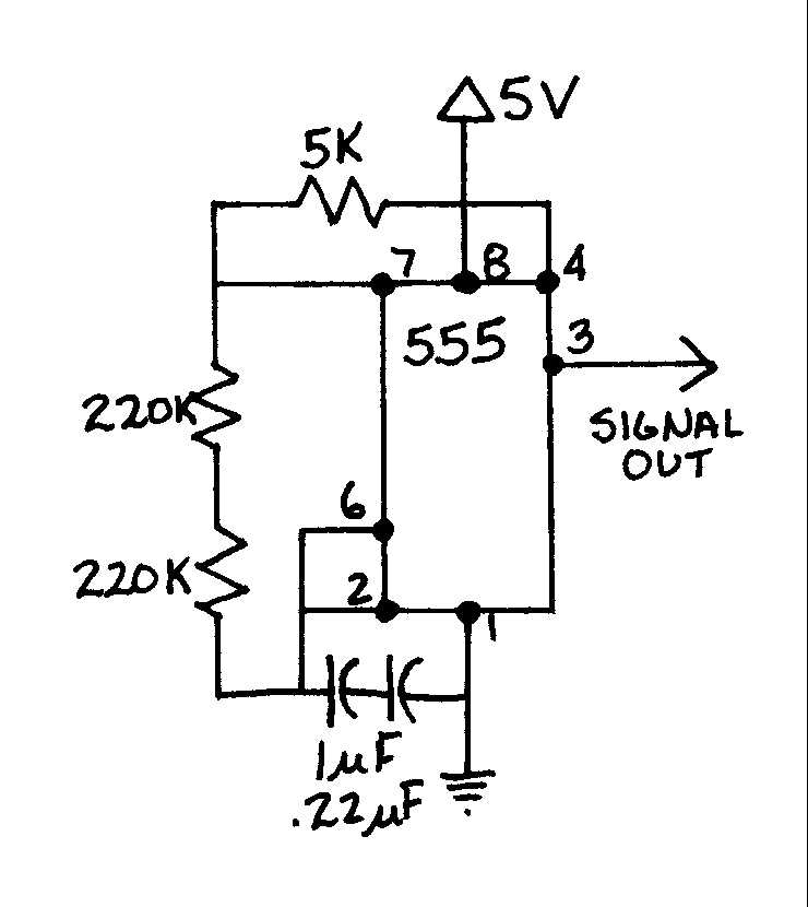
EGR 450 Manufacturing Controls Project
A timing and counting circuit utilizing integrated circuit chips with seven-segment LED displays is employed to show the current lap time, previous lap time, and total number of laps completed on a 1/64th-scale slot car racetrack. A switch activated by...
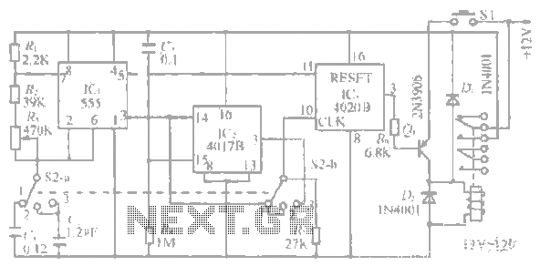
1-20 minutes a timing circuit
The system operates between 10 minutes to 2 hours, featuring a 100-line bell controlled by a multi-gear stick labeled S2 41f. The integrated circuit (IC) functions as a self-excited multivibrator. The device can manage binary pulses ranging from 3 to...
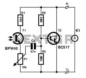
slave flash trigger
The built-in flash of digital cameras is intended for indoor photography. At distances greater than five meters, the light output is often insufficient for satisfactory images. Many cameras lack a hot shoe for an external flash, necessitating the use of...
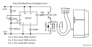
freeze protector circuit
This is a simple freeze protector circuit diagram, also known as a timing circuit. It serves as a hobby project for beginners. This circuit can automatically operate any device after a fixed time once AC power supply is restored. The...
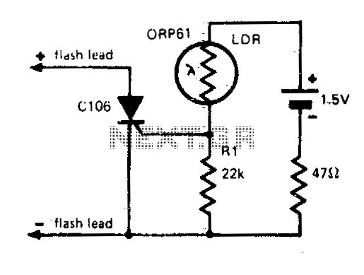
Flash slave driver
In photography, a separate flash, triggered by the light of a master flash, is often required to provide additional light and fill in shadows. The sensitivity of this circuit depends on the proximity of the master flash and the value...
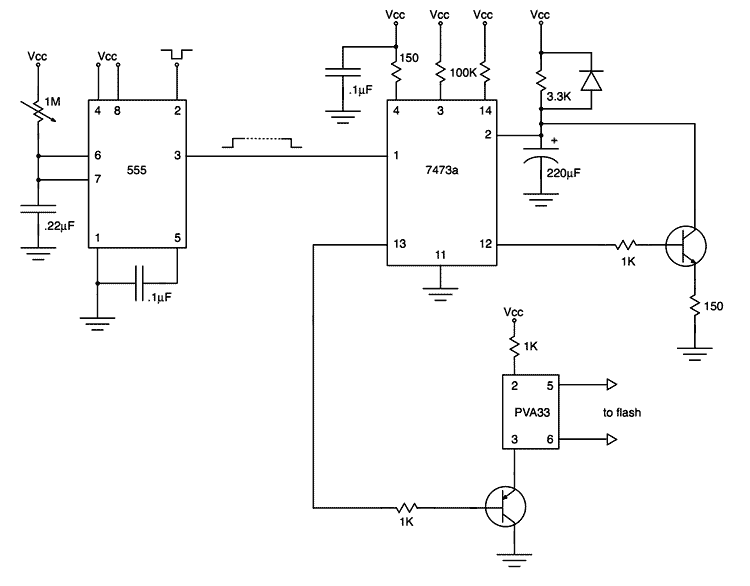
Flash triggering circuit
My first project after assembling an electronic design lab was to build a flash trigger that I could use for high-speed photography. I thought it would be useful to share not only the finished product but also the reasoning that...

Slave Flash Trigger
Using any camera in a dull or dark environment generally requires supplementary light. This is a standard technique, and even where adequate natural lighting exists, conventional film pictures can benefit from enhanced contrast by using a fill-in flash for foreground...
1-20 minutes a timing circuit
The system operates between 10 minutes to 2 hours, featuring a 100-line bell controlled by a multi-gear stick labeled S2 41f. The integrated circuit (IC) functions as a self-excited multivibrator. The device can manage binary pulses ranging from 3 to...
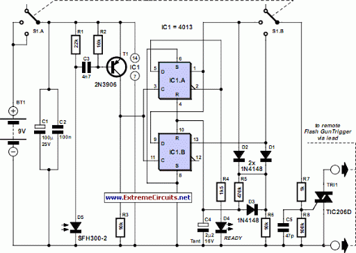
Slave Flash Trigger
Using any camera in a dull or dark environment generally requires the use of supplementary light. This is a standard technique, and even where adequate natural light is not available, additional lighting can enhance image quality.
In electronic circuit design for...