


Optically isolated RS485 circuit diagram of a typical
#RS485
#serial bus
#differential signaling
#optical isolation
#data transmission
#balanced transmission
#common mode rejection
#industrial communication
#network protocol
#signal integrity
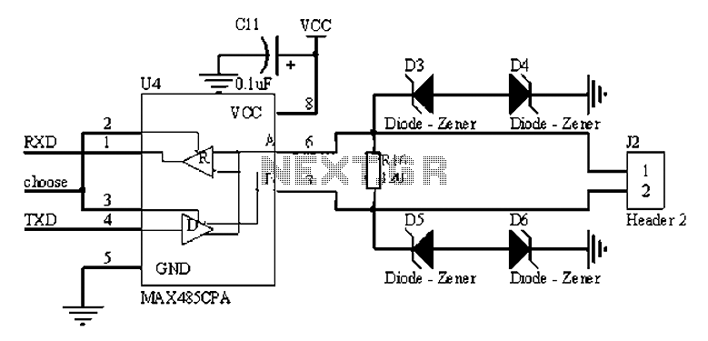
Description: The RS485 bus is a widely used serial bus standard that employs balanced differential transmission and reception techniques, enabling it to effectively suppress common mode interference. It is particularly advantageous for communication distances ranging from tens of meters to several kilometers, making it a popular choice for multi-node systems. The RS485 bus can be categorized into isolated and non-isolated circuits. Isolated circuits generally offer superior performance in terms of interference resistance and system stability, although non-isolated configurations may be suitable in certain scenarios. A typical non-isolated RS485 circuit can be established by directly connecting an RS485 chip to the serial communication port of a microcontroller (MCU) and an I/O control port. In such a configuration, a pull-down bias resistor of 4.7K is added to line B. A matching resistor, typically 120 ohms, is placed in the middle of the circuit, although the exact value may vary depending on the specific transmission cables used. The matching resistor is crucial for ensuring the stability of the entire communication system, and it is common practice to include matching resistors at both the first and last nodes of the communication line. Field personnel can determine whether to use these resistors based on the system's configuration. Additionally, a Transient Voltage Suppressor (TVS) diode, typically rated at 6.8V, is employed for protection against voltage spikes.
The RS485 bus circuit is designed to facilitate robust communication in environments where electrical noise and interference may be present. The differential signaling used in RS485 allows for the detection of signals even in the presence of common mode noise, making it suitable for long-distance communication. The isolated RS485 circuit configuration includes isolation components such as opto-isolators or isolators that provide electrical separation between the communicating devices, enhancing system reliability and safety.
In practical applications, the selection of components such as the RS485 transceiver, termination resistors, and biasing resistors must be made carefully to optimize performance. The RS485 transceiver is responsible for converting the serial data from the MCU into differential signals suitable for transmission over the bus. Proper termination with the matching resistor minimizes signal reflections, which can degrade communication integrity. The pull-down bias resistor on line B ensures that the line remains in a defined state when no devices are actively transmitting, preventing false triggering of receivers.
Additionally, the layout of the circuit board should consider factors such as trace length, impedance matching, and grounding to further reduce noise and enhance signal integrity. When implementing an RS485 bus system, attention to these details will lead to improved performance and reliability in various industrial and commercial applications, including automation systems, data acquisition, and remote monitoring.A, RS485 bus Introduction RS485 bus is a common serial bus standard, using balanced differential transmit and receive mode, and therefore has the ability to suppress common mod e interference. In some of the requirements on the communication distance of tens of meters to kilometers when, RS485 bus is a bus most widely used. But also in the operation of the system of multi-node also has a wide range of applications. Two, RS485 bus describes a typical circuit It can be divided into isolated and non-isolated RS485 circuit as a whole.
Isolated than non-isolated in interference, system stability and other aspects of better performance, but there are some situations you can also use non-isolated. We speak about non-typical circuit isolated and non-isolated circuit is very simple, just a RS485 chip directly with MCU serial communication port and an I/O control port connection can be.
As shown in Figure 1: in line B plus a pull-down bias resistors of 4.7K. Matching resistor R16 is in the middle, typically 120, of course, this depends on your specific transmission cables. (Matching resistor: 485 entire communication system for transmission system stability, we will normally be the first node and last node plus matching resistance so we are generally in the design, you will have a set at each node jumper 120 resistance, as to use or not, by the field staff to set.
of course, specifically how to distinguish between the first node is the last node, have to be on-site experts to answer Oh.) TVS we generally use 6.8V and this we will further explain later.
The RS485 bus circuit is designed to facilitate robust communication in environments where electrical noise and interference may be present. The differential signaling used in RS485 allows for the detection of signals even in the presence of common mode noise, making it suitable for long-distance communication. The isolated RS485 circuit configuration includes isolation components such as opto-isolators or isolators that provide electrical separation between the communicating devices, enhancing system reliability and safety.
In practical applications, the selection of components such as the RS485 transceiver, termination resistors, and biasing resistors must be made carefully to optimize performance. The RS485 transceiver is responsible for converting the serial data from the MCU into differential signals suitable for transmission over the bus. Proper termination with the matching resistor minimizes signal reflections, which can degrade communication integrity. The pull-down bias resistor on line B ensures that the line remains in a defined state when no devices are actively transmitting, preventing false triggering of receivers.
Additionally, the layout of the circuit board should consider factors such as trace length, impedance matching, and grounding to further reduce noise and enhance signal integrity. When implementing an RS485 bus system, attention to these details will lead to improved performance and reliability in various industrial and commercial applications, including automation systems, data acquisition, and remote monitoring.A, RS485 bus Introduction RS485 bus is a common serial bus standard, using balanced differential transmit and receive mode, and therefore has the ability to suppress common mod e interference. In some of the requirements on the communication distance of tens of meters to kilometers when, RS485 bus is a bus most widely used. But also in the operation of the system of multi-node also has a wide range of applications. Two, RS485 bus describes a typical circuit It can be divided into isolated and non-isolated RS485 circuit as a whole.
Isolated than non-isolated in interference, system stability and other aspects of better performance, but there are some situations you can also use non-isolated. We speak about non-typical circuit isolated and non-isolated circuit is very simple, just a RS485 chip directly with MCU serial communication port and an I/O control port connection can be.
As shown in Figure 1: in line B plus a pull-down bias resistors of 4.7K. Matching resistor R16 is in the middle, typically 120, of course, this depends on your specific transmission cables. (Matching resistor: 485 entire communication system for transmission system stability, we will normally be the first node and last node plus matching resistance so we are generally in the design, you will have a set at each node jumper 120 resistance, as to use or not, by the field staff to set.
of course, specifically how to distinguish between the first node is the last node, have to be on-site experts to answer Oh.) TVS we generally use 6.8V and this we will further explain later.

Carrier Current Transmitter For Data Transmission
In this circuit, data at input C is amplified by IC2 and then fed to modulator IC1. IC1 generates two frequencies, depending on the values of C5, I10, R5, Rn, and R6. The frequency f1 is generated if pin 9...
Automatic telephone recording interface circuit optical isolation
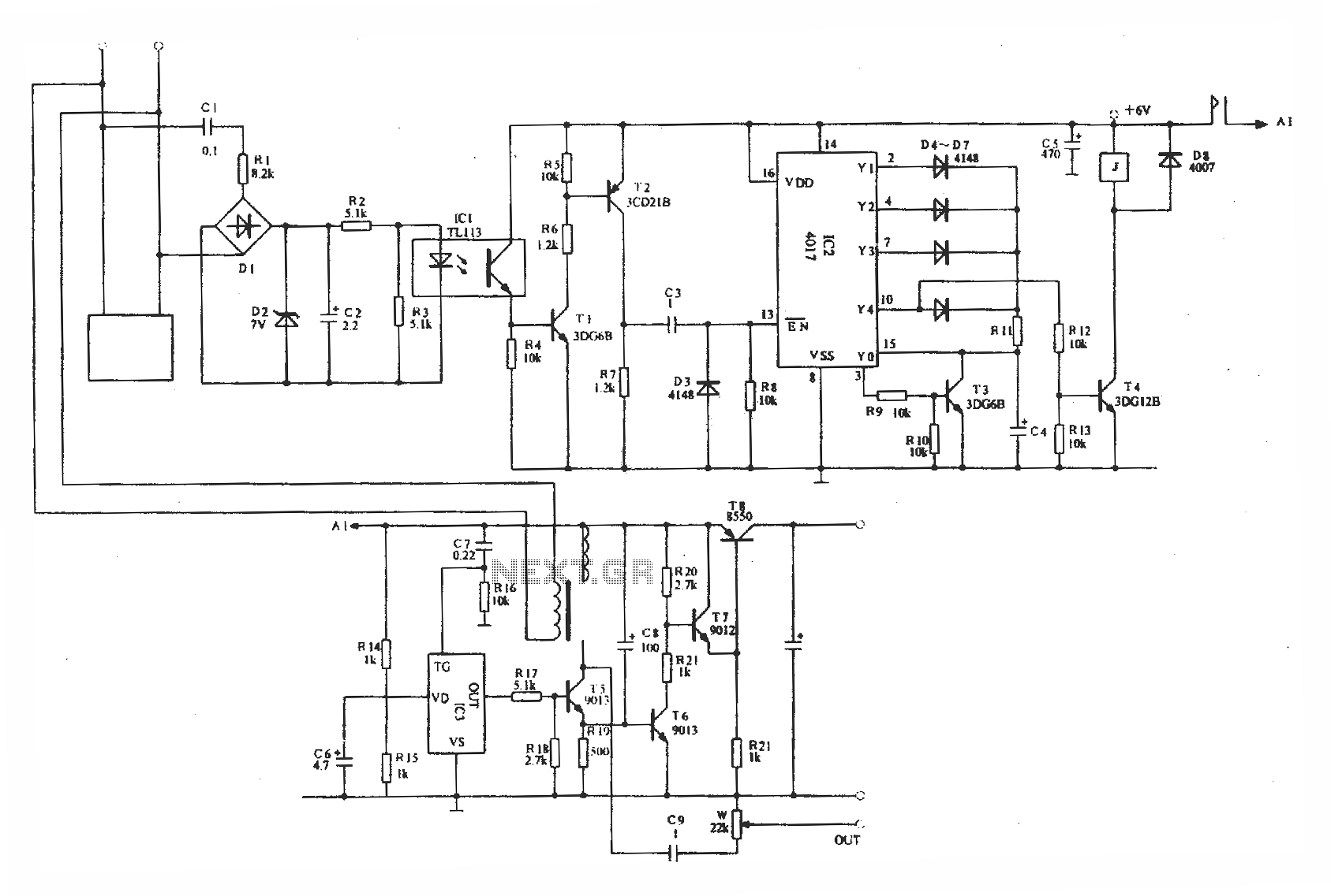
Optically isolated phone automatic recording interface circuit, IC3 voice module.
The optically isolated phone automatic recording interface circuit is designed to capture audio signals from a telephone line while ensuring electrical isolation between the phone line and the recording device. This...
RS485 Library for Windows and Atmel AVR 8-Bit
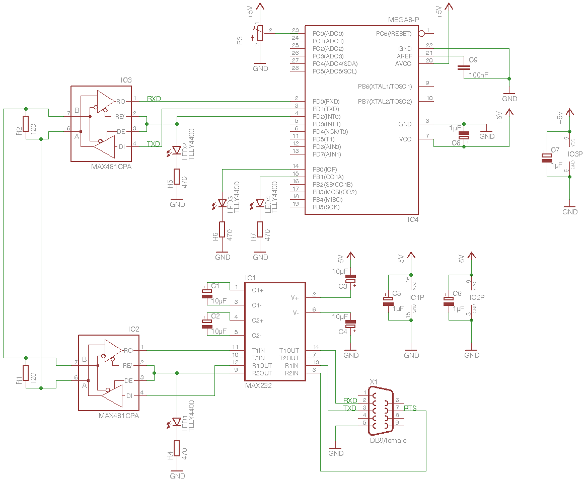
This project implements a half-duplex, master/slave communications protocol based on RS-485 bus hardware. A Windows PC acts as the bus-master, while several Atmel 8-bit AVRs function as bus-slaves. The Windows component is developed in C++, with the ninth data bit...
Automatic telephone recording interface circuit optical isolation
Optically isolated phone automatic recording interface circuit, IC3 voice module.
The optically isolated phone automatic recording interface circuit is designed to capture audio signals from a telephone line while ensuring electrical isolation between the phone line and the recording device. This...
RS485-like multi-drop bus
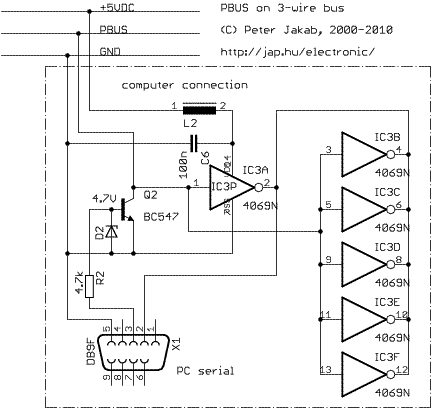
PBUS is an RS485-like multi-drop bus for interconnecting PIC and other microcontroller-driven devices. Protocol and software is written by Jap. Just include a separate pbus library file into your project and add your command handlers for the specific device in...

Carrier-Current Receiver For Data Transmission
This receiver consists of an input network, amplifier IC7, FSK PLL detector IC8, and output amplifier/interface circuits Q2, Q3, IC3A, and IC3B, which include a 1488 Quad RS232 line driver for the carrier-current signal. The tuned amplifier IC7 amplifies this...
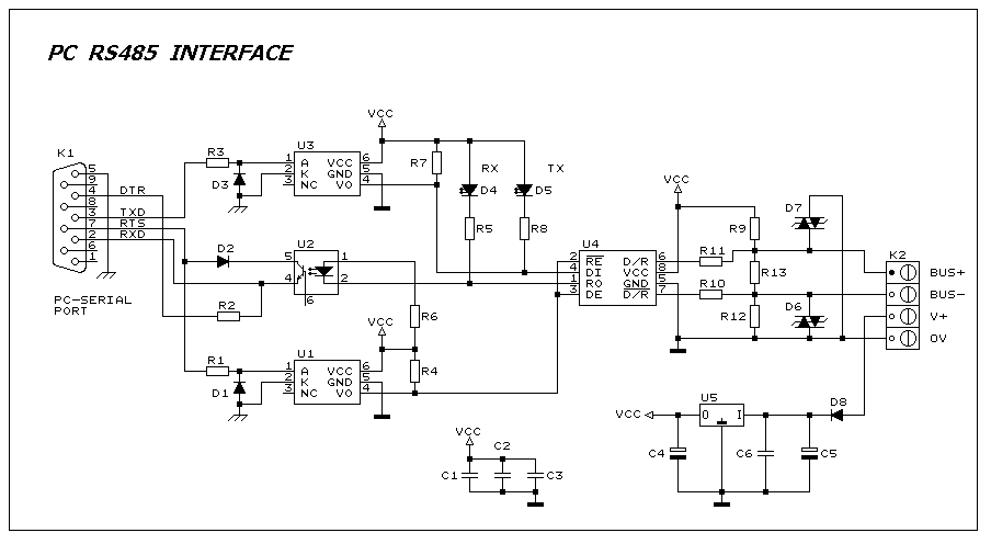
PC RS485 Interface
This interface circuit provides electrically isolated RS485 communication interface to the PC serial port. The isolation circuit protects the PC from direct connection to hazardous voltages. More: Figure 1 shows the circuit diagram of RS485 interface. Connector K1 is linked...
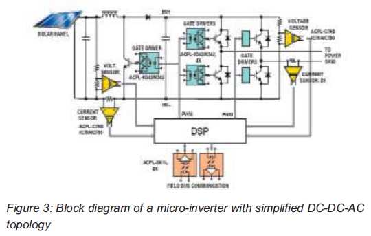
Optical Isolation Amplifiers and Gate Driver Optocouplers
Both help improve efficiency and protect micro-inverters in photovoltaic (PV) solar applications. In 2009, the residential solar photovoltaic (PV) inverter market represented 90 percent of the total PV.
The integration of micro-inverters in photovoltaic solar applications has significantly enhanced system efficiency...
RS485-like multi-drop bus
PBUS is an RS485-like multi-drop bus for interconnecting PIC and other microcontroller-driven devices. Protocol and software is written by Jap. Just include a separate pbus library file into your project and add your command handlers for the specific device in...