


RS-232 to RS-485 converter circuit usin MAX487
#RS-232
#RS-485
#MAX487
#serial communication
#data converter
#interface
#long-distance communication
#industrial communication
#protocol converter
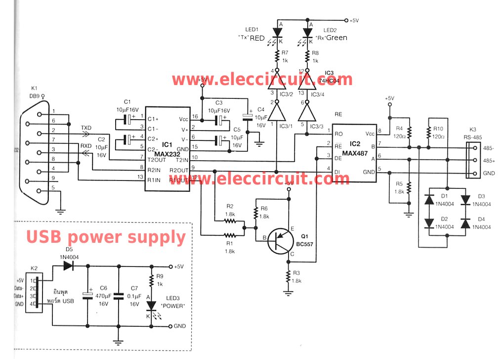
Description: The RS-232 system connection is faster and easier, but the distance is limited. Therefore, this project involves using an RS-485 system with an RS-232 to RS-485 converter.
The RS-232 to RS-485 converter project aims to extend the communication range and improve the reliability of data transmission in serial communication systems. The RS-232 standard is typically limited to short distances, usually up to 15 meters, and is not suitable for multi-drop configurations. In contrast, RS-485 supports longer distances, up to 1200 meters, and allows for multiple devices to communicate on the same bus, making it ideal for industrial applications.
The converter works by translating the voltage levels of the RS-232 signals into the differential signals used by RS-485. This is accomplished using a dedicated RS-232 to RS-485 converter chip, which handles the necessary level shifting and signal conditioning. The circuit typically includes the following components:
1. **RS-232 Connector**: A DB9 or DB25 connector is used to interface with the RS-232 device. The connector facilitates the connection of the RS-232 signals, including TX (transmit), RX (receive), GND (ground), and optionally control signals like RTS (Request to Send) and CTS (Clear to Send).
2. **Level Shifting Circuit**: The converter chip implements a level shifting mechanism that converts the single-ended RS-232 signals to differential signals suitable for RS-485 communication. This often involves using operational amplifiers or dedicated level shifter ICs.
3. **RS-485 Connector**: A terminal block or DB9 connector is used for RS-485 communication. The RS-485 signals (A and B) are transmitted differentially, which helps to reduce noise and allows for longer transmission distances.
4. **Power Supply**: The converter may require a power supply, typically +5V or +12V, depending on the specifications of the converter chip used. This supply powers the logic circuitry and the level shifting components.
5. **Termination Resistors**: In longer RS-485 networks, termination resistors may be added at the ends of the communication line to prevent signal reflections, ensuring better signal integrity.
6. **Isolation (optional)**: For improved protection against electrical noise and ground loops, isolation circuitry can be incorporated, which separates the RS-232 side from the RS-485 side.
This converter allows seamless communication between RS-232 devices and RS-485 networks, enabling the integration of legacy systems with modern multi-drop serial communication systems. The design must ensure proper grounding and shielding to minimize interference, especially in industrial environments where electromagnetic interference (EMI) can be prevalent.RS-232 system connection faster and easier, But distance is not far. so to change to use the system RS-485 with this RS-232 to RS-485 converter projects. It..
The RS-232 to RS-485 converter project aims to extend the communication range and improve the reliability of data transmission in serial communication systems. The RS-232 standard is typically limited to short distances, usually up to 15 meters, and is not suitable for multi-drop configurations. In contrast, RS-485 supports longer distances, up to 1200 meters, and allows for multiple devices to communicate on the same bus, making it ideal for industrial applications.
The converter works by translating the voltage levels of the RS-232 signals into the differential signals used by RS-485. This is accomplished using a dedicated RS-232 to RS-485 converter chip, which handles the necessary level shifting and signal conditioning. The circuit typically includes the following components:
1. **RS-232 Connector**: A DB9 or DB25 connector is used to interface with the RS-232 device. The connector facilitates the connection of the RS-232 signals, including TX (transmit), RX (receive), GND (ground), and optionally control signals like RTS (Request to Send) and CTS (Clear to Send).
2. **Level Shifting Circuit**: The converter chip implements a level shifting mechanism that converts the single-ended RS-232 signals to differential signals suitable for RS-485 communication. This often involves using operational amplifiers or dedicated level shifter ICs.
3. **RS-485 Connector**: A terminal block or DB9 connector is used for RS-485 communication. The RS-485 signals (A and B) are transmitted differentially, which helps to reduce noise and allows for longer transmission distances.
4. **Power Supply**: The converter may require a power supply, typically +5V or +12V, depending on the specifications of the converter chip used. This supply powers the logic circuitry and the level shifting components.
5. **Termination Resistors**: In longer RS-485 networks, termination resistors may be added at the ends of the communication line to prevent signal reflections, ensuring better signal integrity.
6. **Isolation (optional)**: For improved protection against electrical noise and ground loops, isolation circuitry can be incorporated, which separates the RS-232 side from the RS-485 side.
This converter allows seamless communication between RS-232 devices and RS-485 networks, enabling the integration of legacy systems with modern multi-drop serial communication systems. The design must ensure proper grounding and shielding to minimize interference, especially in industrial environments where electromagnetic interference (EMI) can be prevalent.RS-232 system connection faster and easier, But distance is not far. so to change to use the system RS-485 with this RS-232 to RS-485 converter projects. It..
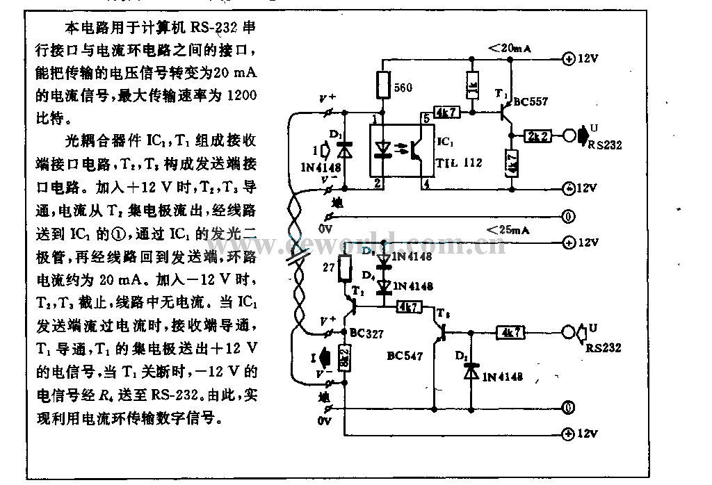
Computer RS-23Z serial interface current loop circuit
This circuit is utilized in RS-232 serial interface and current loop circuit applications. It converts voltage signals into a 20mA current signal, with a maximum transmission rate of 1200 bits per second. The CCD IC1 and transistor T1 form the...
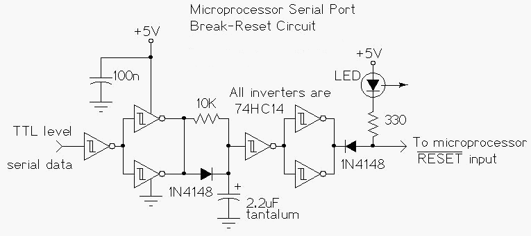
Microprocessor RS-232 Reset
This circuit enables a remote microprocessor to be reset by a controlling host via a remote RS-232 or similar protocol serial line. Utilizing a program loader on the remote host, a program can be downloaded and executed. This functionality allows...
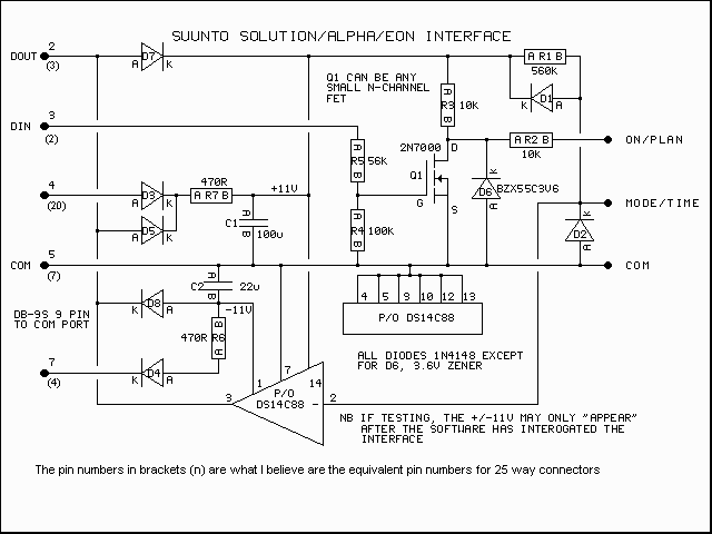
Suunto PC Interface
This page contains GIF images of the circuit diagram for the Solution interface, the PCB artwork, the board layout, a typical side elevation of the assembly, a parts list, some hints, and a brief overview of troubleshooting. This is a...
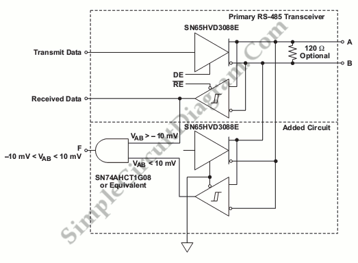
RS-485 Signal Loss Detection
The safety shutdown and fault isolation protocol is critical in various telecommunication, industrial, and data processing systems. It is essential for data sharing.
The safety shutdown and fault isolation protocol serves as a fundamental component in ensuring the reliability and safety...
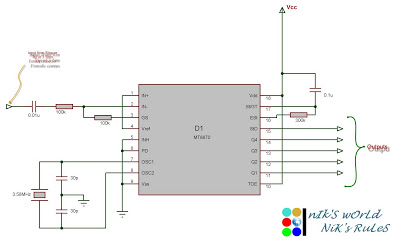
Microcontroller circuits
Connect the serial cable to the serial port. If using a USB to TTL, RS232, or serial converter, plug it into the USB port. Next, short the Tx pin to the Rx pin or the TxD pin to the RxD...
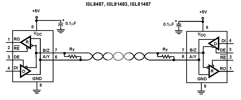
ISL81487 5V Half Duplex 5Mbps RS-485/RS-422 Transceiver
The Intersil RS-485/RS-422 devices are fractional unit load (UL), BiCMOS, 5V powered, single transceivers that comply with both RS-485 and RS-422 standards for balanced communication. This Intersil family is designed for 10% tolerance supplies (4.5V to 5.5V). The ISL81483 and...
Computer RS-23Z serial interface current loop circuit
This circuit is utilized in RS-232 serial interface and current loop circuit applications. It converts voltage signals into a 20mA current signal, with a maximum transmission rate of 1200 bits per second. The CCD IC1 and transistor T1 form the...
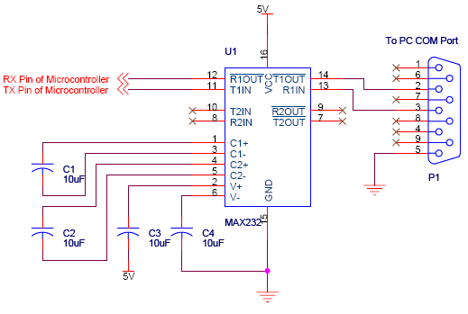
serial communication introduction
Serial communication using UART or USART of a microcontroller 8051 AVR PIC, software implementation of half-duplex UART and MAX232 interfacing with microcontrollers 8051 AVR PIC.
The described system focuses on implementing serial communication via UART (Universal Asynchronous Receiver-Transmitter) or USART (Universal...
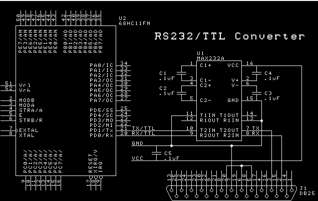
RS-232 to TTL cable with MAX232
Here is a diagram of the internals of the MAX232A. It shows a double charge pump voltage doubler and a +10v to -10v voltage inverter. The voltages output are used to generate the RS-232 compliant signals. The MAX232A has provisions...