


Simple Intercom Circuit Transistor
#transistor
#intercom
#RC amplifier
#pushbutton
#audio communication
#simple circuit
#two-way communication
#DIY electronics
#home communication
#transistor amplifier
Description: The circuit diagram represents a simple yet effective intercom system entirely based on transistors. It consists of three stages along with an RC amplifier. When the pushbutton S2 is pressed, the amplifier circuit around transistor T1 is activated.
The intercom circuit utilizes three transistor stages to amplify audio signals, ensuring clear communication between the stations. The first stage typically involves a microphone connected to the base of the first transistor (T1), which serves as a pre-amplifier. This stage is crucial for picking up the audio signals and converting them into electrical signals.
The second stage amplifies the signal further, using a second transistor (T2) configured in a common emitter arrangement. This configuration provides additional gain and helps to drive the next stage of the circuit. The output from T2 is then fed into an RC (resistor-capacitor) filter that smooths out the signal and eliminates any high-frequency noise that may interfere with audio clarity.
The final stage, which involves the third transistor (T3), acts as a driver stage to power the speaker or output device. This transistor also ensures that the audio signal is strong enough to be heard clearly at the receiving end of the intercom system. The pushbutton switch S2 serves as a control mechanism, allowing the user to activate the circuit and initiate communication.
In summary, this transistor-based intercom circuit design effectively amplifies audio signals through a three-stage amplification process, with the RC filter enhancing signal quality, making it suitable for reliable intercom applications.Circuit diagram is a simple but effective circuit intercom circuit is based entirely on transistors. Circuit diagram is based on three stages plus RC amplifier. When the pushbutton S2 is pressed, the amplifier cord around T1 .
The intercom circuit utilizes three transistor stages to amplify audio signals, ensuring clear communication between the stations. The first stage typically involves a microphone connected to the base of the first transistor (T1), which serves as a pre-amplifier. This stage is crucial for picking up the audio signals and converting them into electrical signals.
The second stage amplifies the signal further, using a second transistor (T2) configured in a common emitter arrangement. This configuration provides additional gain and helps to drive the next stage of the circuit. The output from T2 is then fed into an RC (resistor-capacitor) filter that smooths out the signal and eliminates any high-frequency noise that may interfere with audio clarity.
The final stage, which involves the third transistor (T3), acts as a driver stage to power the speaker or output device. This transistor also ensures that the audio signal is strong enough to be heard clearly at the receiving end of the intercom system. The pushbutton switch S2 serves as a control mechanism, allowing the user to activate the circuit and initiate communication.
In summary, this transistor-based intercom circuit design effectively amplifies audio signals through a three-stage amplification process, with the RC filter enhancing signal quality, making it suitable for reliable intercom applications.Circuit diagram is a simple but effective circuit intercom circuit is based entirely on transistors. Circuit diagram is based on three stages plus RC amplifier. When the pushbutton S2 is pressed, the amplifier cord around T1 .
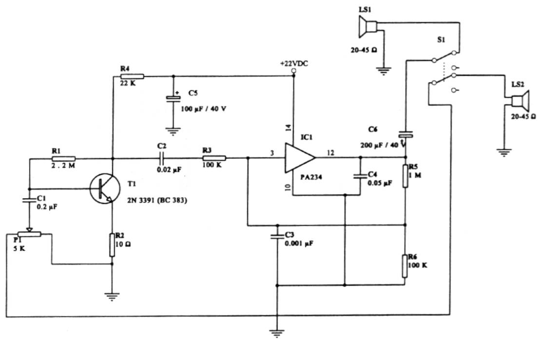
Intercommunication (Intercom) circuit
This intercom circuit is versatile and can be utilized in various applications. It operates at 22V, although it may function at a lower voltage (experimental testing is suggested). The circuit utilizes a loudspeaker with an impedance of 20-45 Ohms on...
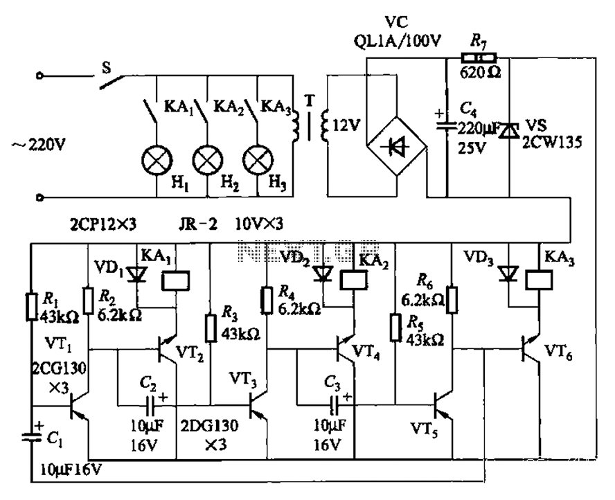
Alternately flashing lights chain multiple sets of high-power circuit 2
The transistors VTi, VT3, and VTs, along with the RC components, form three distinct multi-resonator oscillators. The oscillation frequency levels are dependent on the values of Ri, R3, Rs, and Cl, as well as Cz and C3s.
The circuit comprises three...
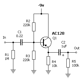
Leaky Transistor Buffer
The wah pedal operates before the amplifier but produces a low volume and a scratchy sound when the pedal is rocked back and forth. It functions correctly without the buffer. When placed in front of a Fuzz Face, no sound...
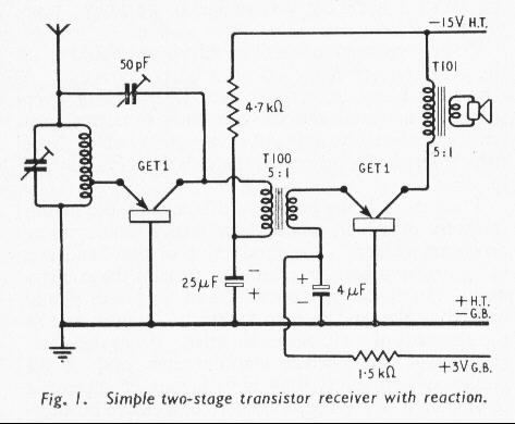
early GEC transistor radio
The world's first practical crystal amplifying device was introduced in 1948, marking the beginning of commercially available transistor radios in Britain. At that time, an average radio enthusiast or constructor would have been adjusting to new miniature glass valves, exploring...
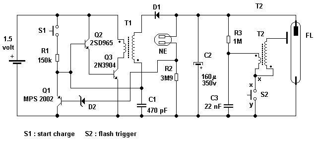
Camera flash circuit
A simple transistor generator and transformer converts a 1.5V battery voltage to several hundred volts. This high voltage current then passes through a diode, which rectifies the current to DC. This DC current is stored in a relatively large capacitor....
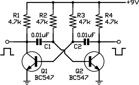
Two-phase squarewave oscillator
This circuit is one of the simplest to implement but can be challenging to comprehend. It consists of a two-transistor oscillator known as an astable multivibrator, which generates a square wave output that is out of phase. Initially, it is...
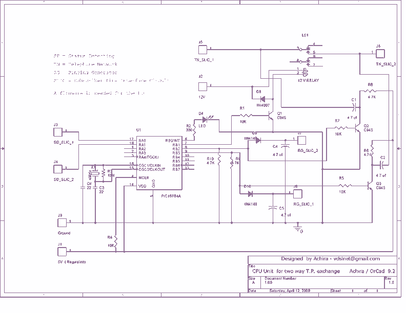
Bi-directional intercom system
This is a very small telephone exchange attached only two ordinary Tele phones. Fully bi-directional facility with an intercom system. When a phone is in off hook condition, Exchange will detect it & send ringing pulse to other phone. When...
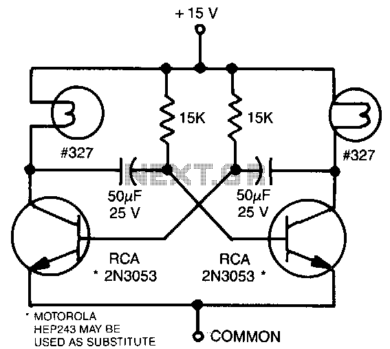
Transistor-flasher
This astable multivibrator utilizes incandescent lamps instead of collector load resistors. The lamps flash on and off alternately.
The circuit operates as an astable multivibrator, which is a type of oscillator that continuously switches between its high and low states without...
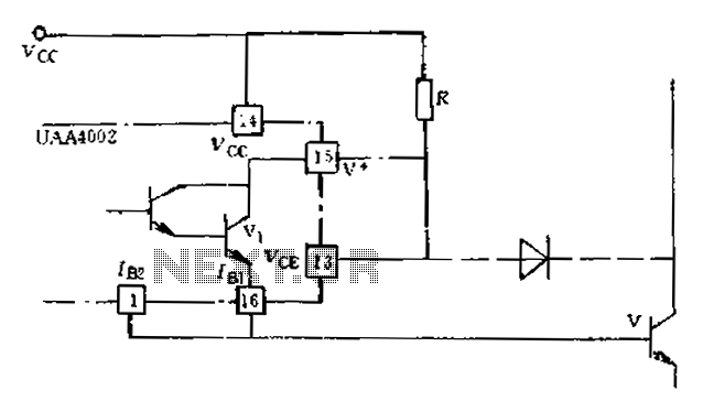
Anti-saturation function delete circuit schematics
Anti-saturation devices have been removed from the UAA4002 routine applications. The base current of the switching transistor, which is driven by another transistor, is automatically adjusted. This adjustment allows the power transistors to operate in critical saturation. However, when the...