


Straight and Cross Cable LAN
#LAN
#UTP cable
#crossover cable
#EIA/TIA 568A
#EIA/TIA 568B
#straight cable
#networking
#computer connection
#HUB
#switch
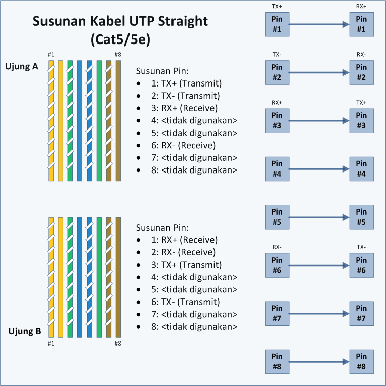
Description: To connect two computers or to connect two hubs/switches using UTP cable, a crossover cable can be used. When connecting computers to a hub or switch, straight cables should be utilized. A straight cable is defined as a cable that follows the same wiring standards on both ends, which can be either EIA/TIA 568A or EIA/TIA 568B. This means that the color sequence of the wires on both ends is identical. In straight cables, pin 1 at one end connects to pin 1 at the other end, pin 2 connects to pin 2, and so forth. When a PC transmits data on pins 1 and 2 through the straight cable to the switch, the switch receives the data on pins 1 and 2 as well. However, since pins 1 and 2 on the switch are not used for sending data, the configuration allows for a different connection where pins 1 and 2 at one end are connected to pins 3 and 6 at the opposite end. Therefore, pins 1 and 2 on each end of the cable are designated for data transmission, while pins 3 and 6 are used for data reception, as pins 1 and 2 are connected to the opposite pins 3 and 6. To determine whether a cable is a crossover or straight, one can simply examine one end of the cable. If the color sequence for pin 1 is White Green, then the cable is a crossover; however, if the other end also has the same color sequence of White Green for pin 1, then it is a straight cable. Most cables typically adhere to the EIA/TIA 568B standard on both ends. Crossover cables are required for connecting two hubs/switches or for direct connections between two computers. If the hub/switch or Network Interface Card (NIC) has an uplink port or MDI/MDI-X capability, straight cables can be used to connect to a standard port on the hub/switch or NIC.
The described network cabling setup highlights the importance of understanding the distinctions between crossover and straight cables in Ethernet networking. Crossover cables are essential for direct connections between two similar devices, such as two computers or two hubs, as they enable the correct pin configuration for data transmission and reception. The pinout configuration of a crossover cable typically involves connecting the transmit pins of one device to the receive pins of the other, facilitating seamless communication.
In contrast, straight cables are utilized for connections involving dissimilar devices, such as a computer to a switch or hub. The pinout remains consistent across both ends, allowing devices to communicate effectively without signal interference. The EIA/TIA 568A and EIA/TIA 568B standards provide the necessary guidelines for wiring these cables, ensuring compatibility and performance across various networking environments.
When designing or troubleshooting a network, it is crucial to verify the cable type being used, as using the incorrect type can lead to connectivity issues. For example, connecting two computers directly with a straight cable will result in a failure to communicate, as the transmit and receive pins will not align correctly. Conversely, utilizing a crossover cable in situations where a straight cable is required can also lead to communication breakdowns.
In modern networking hardware, many devices are equipped with auto-sensing ports, known as MDI/MDI-X, which can automatically detect the type of cable connected and adjust accordingly. This feature simplifies network setup and reduces the likelihood of cabling errors, allowing for greater flexibility in network design. Nevertheless, understanding the fundamental differences between cable types remains a vital skill for network engineers and technicians to ensure optimal network performance and reliability.To connect two computers or connecting two HUB / switch with UTP cable, can use a crossover cable. If you connect computers to the HUB / switch, use straight cables. Straight cable is a term for a cable that uses the same standards on both ends of its wires, could EIA / TIA 568A or EIA / TIA 568B on both ends of the cable. Simply put, the sequence of colors on both ends of the same. In straight cables, pin 1 at one end of the cable connected to pin 1 on the other end, pin 2 connected to pin 2 at the other end, and so on. So, when the PC sends data on pin 1 and 2 via the cable straight into the switch, the switch receives data on pins 1 and 2.
Well, because pins 1 and 2 on the switch will not be used to send data as well as pins 1 and 2 on the PC, then switch In the drawing, pins 1 and 2 at the end A is connected to pins 3 and 6 at the end of B, as well as pins 1 and 2 at the end B is connected to pins 3 and 6 at the end of A. Thus, pins 1 and 2 at each end of the cable used to transmit data, while pins 3 and 6 on each end of the cable used to receive data, because the pins 1 and 2 are connected as opposed to pins 3 and 6.
To identify whether a crossover or straight cable is to only see one end of the cable. If the sequence of colors of the wires on pin 1 is White Green, then the cable is a crossover (although if the other end also has the same color sequence that is White Green as pin 1, then the cable is a Straight). But fortunately, most cables use a standard EIA / TIA 568B on both ends of the cord. To connect the two HUB / switch, or connect two computers directly needed a crossover cable. But if the HUB / switch or Network Interface Card (NIC) or other network equipment to provide Uplinkport or MDI / MDI-X you can use straight cables for connecting to a regular port on the HUB / switch or Network Interface Card or other network equipment.
The described network cabling setup highlights the importance of understanding the distinctions between crossover and straight cables in Ethernet networking. Crossover cables are essential for direct connections between two similar devices, such as two computers or two hubs, as they enable the correct pin configuration for data transmission and reception. The pinout configuration of a crossover cable typically involves connecting the transmit pins of one device to the receive pins of the other, facilitating seamless communication.
In contrast, straight cables are utilized for connections involving dissimilar devices, such as a computer to a switch or hub. The pinout remains consistent across both ends, allowing devices to communicate effectively without signal interference. The EIA/TIA 568A and EIA/TIA 568B standards provide the necessary guidelines for wiring these cables, ensuring compatibility and performance across various networking environments.
When designing or troubleshooting a network, it is crucial to verify the cable type being used, as using the incorrect type can lead to connectivity issues. For example, connecting two computers directly with a straight cable will result in a failure to communicate, as the transmit and receive pins will not align correctly. Conversely, utilizing a crossover cable in situations where a straight cable is required can also lead to communication breakdowns.
In modern networking hardware, many devices are equipped with auto-sensing ports, known as MDI/MDI-X, which can automatically detect the type of cable connected and adjust accordingly. This feature simplifies network setup and reduces the likelihood of cabling errors, allowing for greater flexibility in network design. Nevertheless, understanding the fundamental differences between cable types remains a vital skill for network engineers and technicians to ensure optimal network performance and reliability.To connect two computers or connecting two HUB / switch with UTP cable, can use a crossover cable. If you connect computers to the HUB / switch, use straight cables. Straight cable is a term for a cable that uses the same standards on both ends of its wires, could EIA / TIA 568A or EIA / TIA 568B on both ends of the cable. Simply put, the sequence of colors on both ends of the same. In straight cables, pin 1 at one end of the cable connected to pin 1 on the other end, pin 2 connected to pin 2 at the other end, and so on. So, when the PC sends data on pin 1 and 2 via the cable straight into the switch, the switch receives data on pins 1 and 2.
Well, because pins 1 and 2 on the switch will not be used to send data as well as pins 1 and 2 on the PC, then switch In the drawing, pins 1 and 2 at the end A is connected to pins 3 and 6 at the end of B, as well as pins 1 and 2 at the end B is connected to pins 3 and 6 at the end of A. Thus, pins 1 and 2 at each end of the cable used to transmit data, while pins 3 and 6 on each end of the cable used to receive data, because the pins 1 and 2 are connected as opposed to pins 3 and 6.
To identify whether a crossover or straight cable is to only see one end of the cable. If the sequence of colors of the wires on pin 1 is White Green, then the cable is a crossover (although if the other end also has the same color sequence that is White Green as pin 1, then the cable is a Straight). But fortunately, most cables use a standard EIA / TIA 568B on both ends of the cord. To connect the two HUB / switch, or connect two computers directly needed a crossover cable. But if the HUB / switch or Network Interface Card (NIC) or other network equipment to provide Uplinkport or MDI / MDI-X you can use straight cables for connecting to a regular port on the HUB / switch or Network Interface Card or other network equipment.
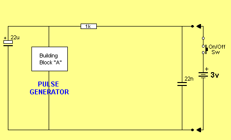
Mini Tracker
A grasshopper is a switch that can activate at any moment. A plastic piece is positioned between two switch contacts to keep them apart, connected to a cotton thread fixed to the floor. When the object is moved, the cotton...
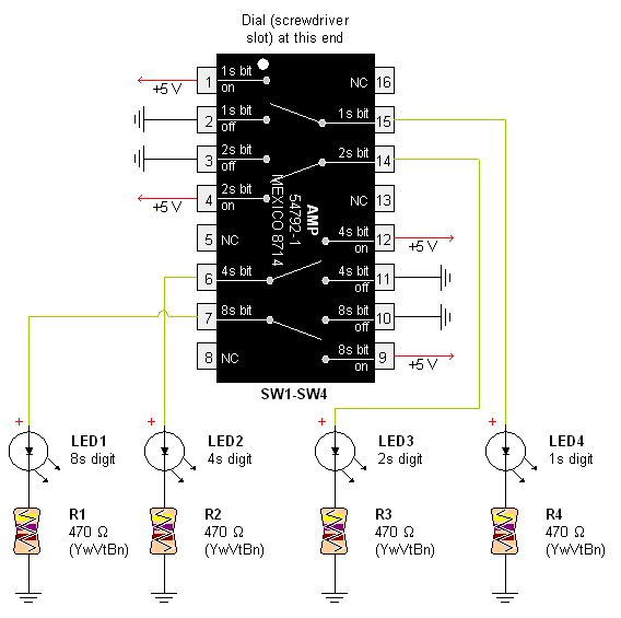
AMP Hexadecimal Rotary Switch
Pictures and a sample schematic (including pinouts) of an AMP hexadecimal (16-position) switch with a screw slot actuator.
The AMP hexadecimal switch is a 16-position rotary switch designed for applications requiring multiple selectable options. This switch features a screw slot actuator...
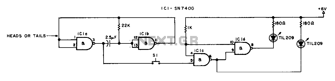
heads or tails
The switch must be a push-to-make, release-to-break type.
An effective circuit utilizing a push-to-make, release-to-break switch can be designed for various applications, particularly in control systems where momentary activation is required. This type of switch, often referred to as a momentary...
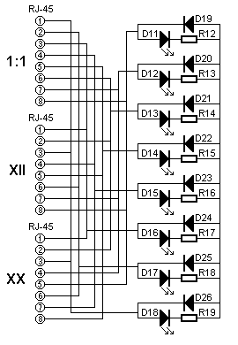
UTP cabel tester
The UTP Cable Tester is designed for multiple applications, primarily to test UTP network cables. It can also assist in identifying the correct cable from a large bundle of similar cables. The circuit can be adapted to test any type...
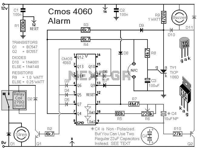
How To Build A Simple Code-Operated Switch
This is a simplified version of the Universal Keypad-Operated Switch. The design has been modified to reduce circuit complexity and the number of components required, resulting in somewhat less secure code functionality. However, it remains adequate for many applications. The...
UTP cabel tester
The UTP Cable Tester is designed for multiple applications, primarily to test UTP network cables. It can also assist in identifying the correct cable from a large bundle of similar cables. The circuit can be adapted to test any type...
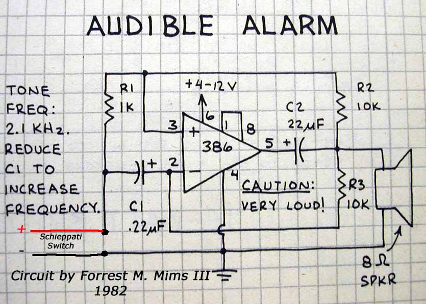
Schiepatti Switch
A highly versatile switch that can be controlled from any channel on a typical Futaba or JR radio setup. This switch was designed to trigger the shutter on digital cameras without the need for a servo attached to the camera....
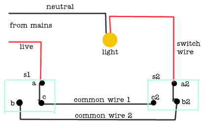
2 Way Switch Wire Electrical
The following circuit illustrates a 2-way switch wiring electrical circuit diagram. Features include the ability to turn on the lights using switch S1, which has three terminals.
The 2-way switch circuit is commonly used in residential and commercial applications to control...
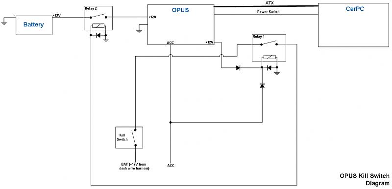
Power Supply/OPUS Kill Switch
After searching for a few days, a solution for this idea has not been found. A switch panel is being created in the dashboard containing four switches.
The switch panel design for the dashboard involves integrating four switches that can control...