


CGA to SCART Adapter
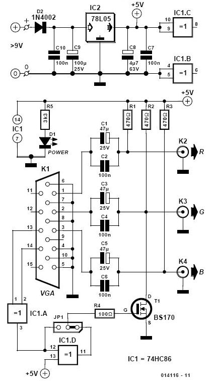
Description: The CGA to SCART adapter offers significant advantages, including the absence of a separate power source and minimal external components, which can be conveniently integrated into the SCART connector. The signals from the R, G, and B pins of the CGA board are converted from TTL levels to SCART levels using resistors R4, R5, and R6, while also accounting for the input impedance (75 ohms) of the SCART interface. Although the output impedance of the voltage dividers formed is not precisely 75 ohms as specified for SCART inputs, practical performance indicates that this discrepancy does not lead to substantial differences. Resistors R1, R2, and R3 connected to pin 6 of the CGA input and the R, G, and B pins of the SCART connector facilitate a 50% reduction in brightness when pin 6 is active. Additionally, synchronization pulses from the horizontal and vertical outputs of the CGA board are used, along with resistors R7 to R11 and transistor T1, to generate a composite sync signal and a signal suitable for television display.
The CGA to SCART adapter circuit is designed to accommodate the video signal conversion requirements between CGA (Color Graphics Adapter) and SCART (Syndicat des Constructeurs d'Appareils Radiorécepteurs et de Télévision) standards. The circuit primarily utilizes resistive voltage dividers to adjust the signal levels appropriately. The resistors R4, R5, and R6 are crucial in transforming the TTL-level signals from the CGA output to the required SCART levels, ensuring compatibility with the SCART input specifications.
The impedance matching is addressed through the configuration of these resistors, which, while not achieving an exact 75-ohm output, maintain signal integrity sufficiently for practical applications. The use of R1, R2, and R3 serves to modulate the brightness of the output signal, allowing for dynamic adjustment based on the state of pin 6. This feature enhances the adaptability of the adapter in various display scenarios, particularly when dealing with older CRT televisions that may not handle high brightness levels well.
Moreover, the synchronization aspect of the video signal is critical for proper display functionality. The circuit employs resistors R7 to R11 in conjunction with transistor T1 to combine the horizontal and vertical sync pulses from the CGA board, creating a composite sync signal. This signal is essential for synchronizing the display output with the video signal, ensuring that the image is rendered correctly on SCART-compatible televisions.
In summary, the CGA to SCART adapter is a compact and efficient solution for interfacing CGA video signals with SCART inputs, effectively managing signal levels, impedance, and synchronization to deliver a functional output suitable for a variety of display devices. The design emphasizes simplicity and effectiveness, making it an ideal choice for retro gaming and vintage computer applications.CGA to SCART adapter has great advantages as it does not require separate power source and that uses very few external components, which can be easily adapted in the SCART connector. The signals from R, G and B pins of the CGA`s board are converted from TTL levels to SCART levels with resistors R4, R5 and R6 and entry`s impedance (75 ©) of scart
inputs. Output Impedance of voltage dividers thus created is not exactly 75 © as specified for SCART inputs, but in practice the behavior seems to result not big differences. R1-R3 resistors from pin 6 of the CGA`s entrance and pins R, G and B of the SCART connector ensure reduction of 50% of brightness when pin 6 active.
From synchronization pulses on horizontal and vertical of CGA board it creates, with the help of R7-R11 ²s and T1, a composite signal timing (SYNC) and a signal remission for TV.
The CGA to SCART adapter circuit is designed to accommodate the video signal conversion requirements between CGA (Color Graphics Adapter) and SCART (Syndicat des Constructeurs d'Appareils Radiorécepteurs et de Télévision) standards. The circuit primarily utilizes resistive voltage dividers to adjust the signal levels appropriately. The resistors R4, R5, and R6 are crucial in transforming the TTL-level signals from the CGA output to the required SCART levels, ensuring compatibility with the SCART input specifications.
The impedance matching is addressed through the configuration of these resistors, which, while not achieving an exact 75-ohm output, maintain signal integrity sufficiently for practical applications. The use of R1, R2, and R3 serves to modulate the brightness of the output signal, allowing for dynamic adjustment based on the state of pin 6. This feature enhances the adaptability of the adapter in various display scenarios, particularly when dealing with older CRT televisions that may not handle high brightness levels well.
Moreover, the synchronization aspect of the video signal is critical for proper display functionality. The circuit employs resistors R7 to R11 in conjunction with transistor T1 to combine the horizontal and vertical sync pulses from the CGA board, creating a composite sync signal. This signal is essential for synchronizing the display output with the video signal, ensuring that the image is rendered correctly on SCART-compatible televisions.
In summary, the CGA to SCART adapter is a compact and efficient solution for interfacing CGA video signals with SCART inputs, effectively managing signal levels, impedance, and synchronization to deliver a functional output suitable for a variety of display devices. The design emphasizes simplicity and effectiveness, making it an ideal choice for retro gaming and vintage computer applications.CGA to SCART adapter has great advantages as it does not require separate power source and that uses very few external components, which can be easily adapted in the SCART connector. The signals from R, G and B pins of the CGA`s board are converted from TTL levels to SCART levels with resistors R4, R5 and R6 and entry`s impedance (75 ©) of scart
inputs. Output Impedance of voltage dividers thus created is not exactly 75 © as specified for SCART inputs, but in practice the behavior seems to result not big differences. R1-R3 resistors from pin 6 of the CGA`s entrance and pins R, G and B of the SCART connector ensure reduction of 50% of brightness when pin 6 active.
From synchronization pulses on horizontal and vertical of CGA board it creates, with the help of R7-R11 ²s and T1, a composite signal timing (SYNC) and a signal remission for TV.
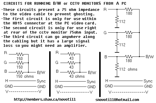
RGB To Monochrome converter
Often you can get away with running a monochrome monitor on GREEN, but this looks real crappy when viewing color images. These simple resistor networks allow you to display R+G+B on a B/W or CCTV monitor without ghosting. Be sure...
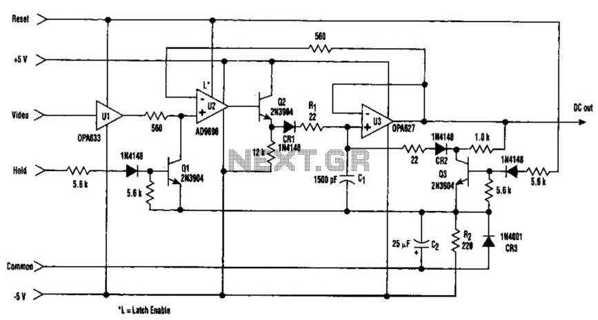
Fast Video Signal Amplitude Measurer Circuit
The amplitude of a video signal can be measured using a straightforward circuit that functions as a modified standard peak detector. This device is capable of verifying RGB signals produced by video RAMDACs. U1 is a high-speed buffer, while U2...
RGB To Monochrome converter
Often you can get away with running a monochrome monitor on GREEN, but this looks real crappy when viewing color images. These simple resistor networks allow you to display R+G+B on a B/W or CCTV monitor without ghosting. Be sure...
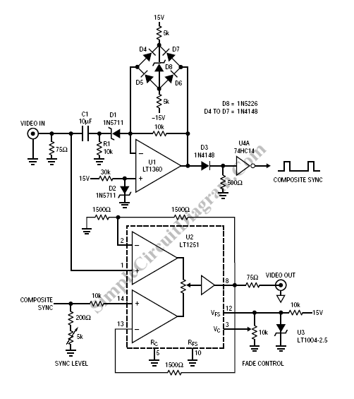
Video Fader Circuit
Fading a video signal cannot be achieved merely by attenuating the composite signal, as the synchronization signal may fall below an unacceptable level.
Fading a video signal involves a careful adjustment of both the luminance and chrominance components while maintaining...
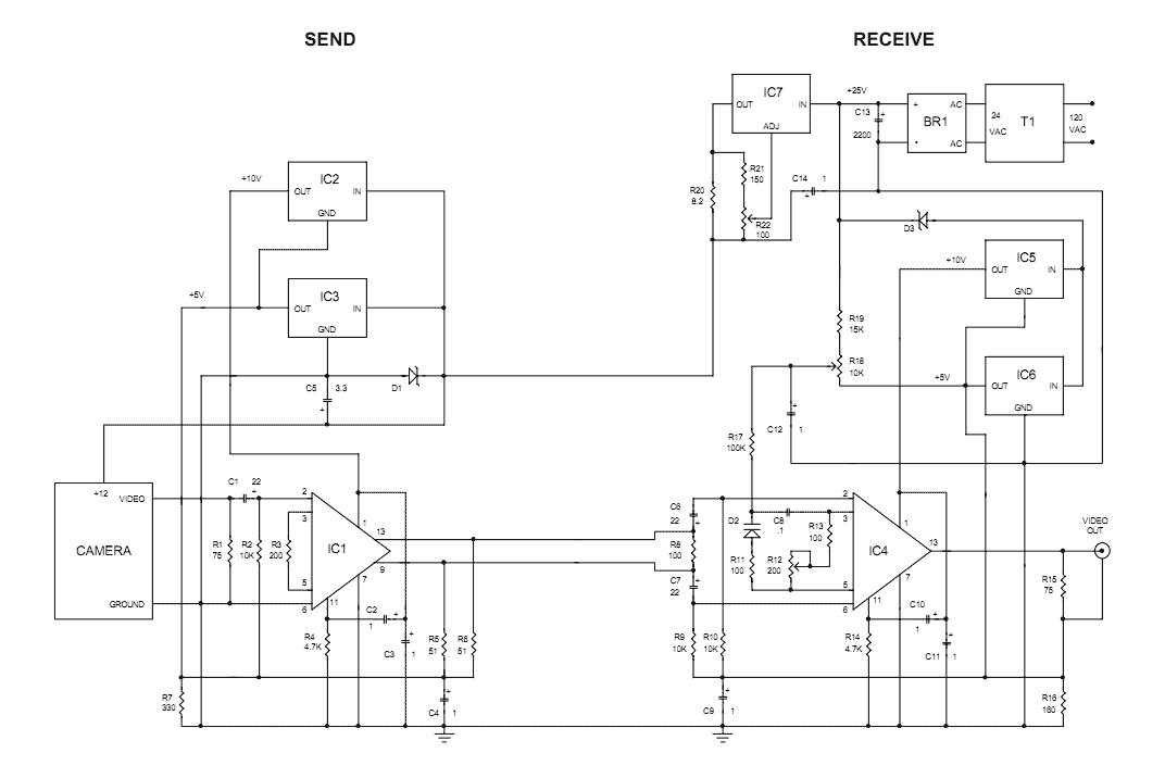
video on telephone line wires
The Videowire converts a baseband video signal into a low impedance differential signal that can be sent over ordinary four conductor telephone wire. A send board mounted close to the camera generates the differential signal and a receive board near...
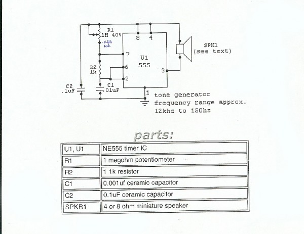
Circuits
To prevent soldering errors, students were instructed to place all their resistors on the board first. Once their placements were verified, they could proceed with soldering. Capacitors were next, followed by LEDs and other components. The middle school class demonstrated...
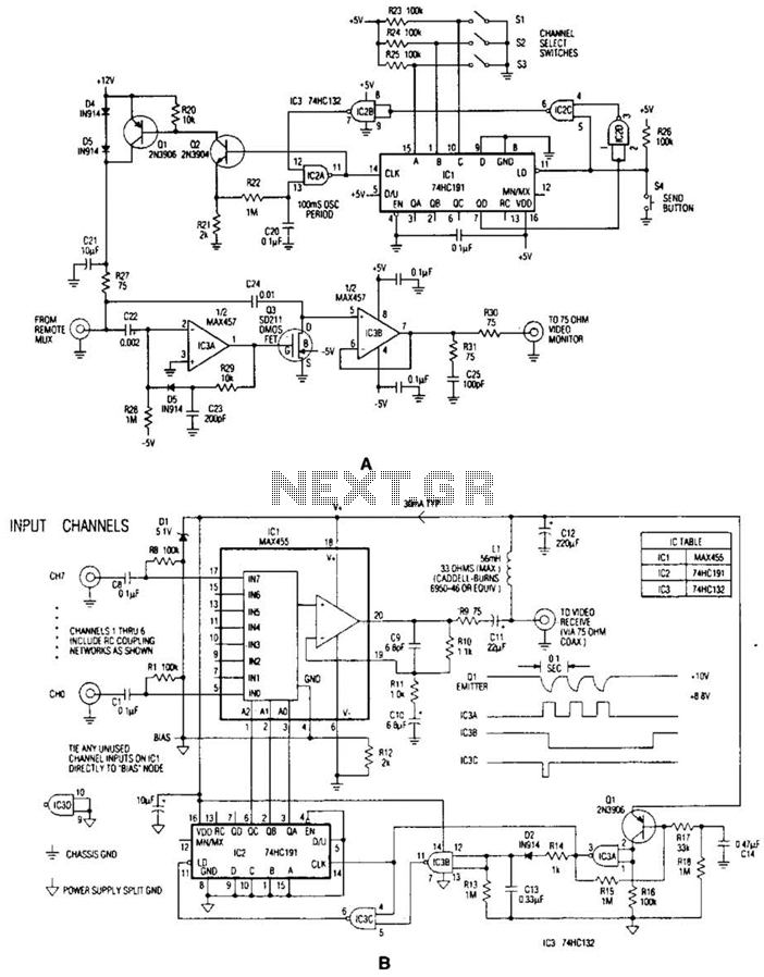
Video Signal Carrier Circuit
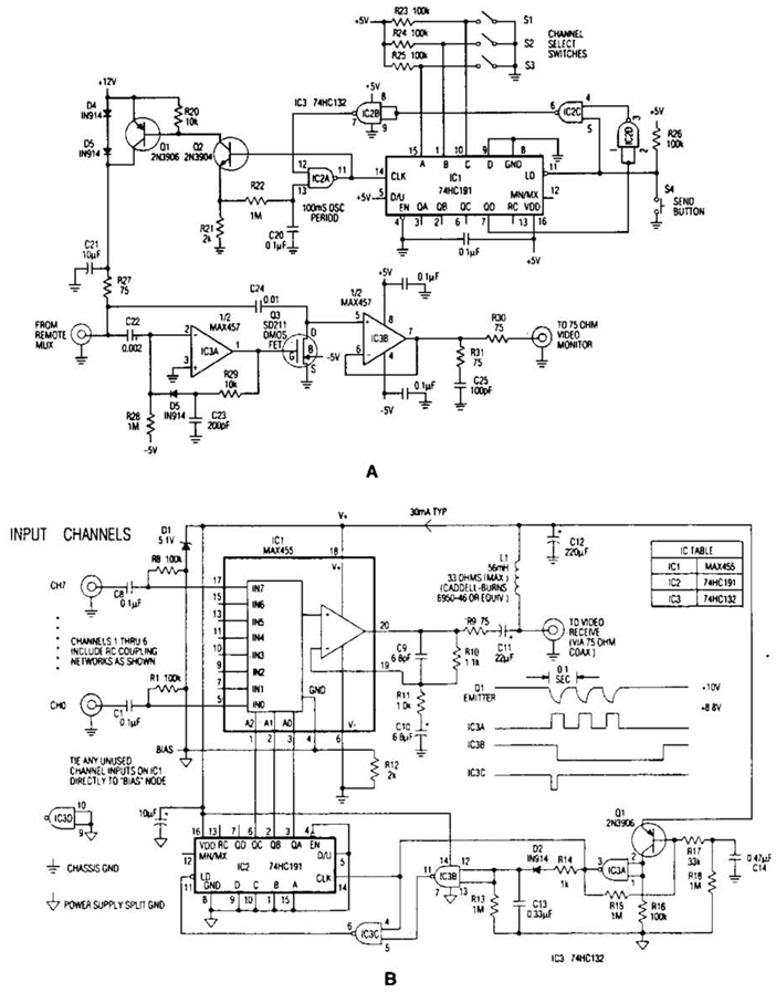
In the video system illustrated in Figures A and R, a single coaxial cable transmits power to a remote location, selects one of eight video channels, and returns the selected signal. This system can choose from several remote surveillance camera...
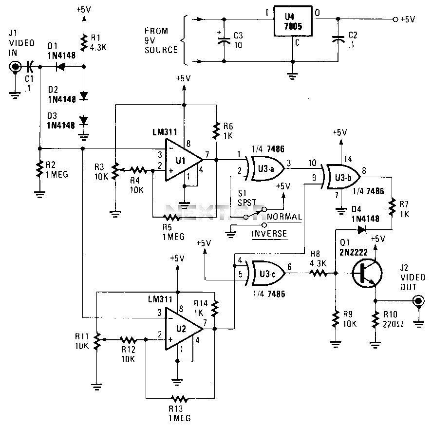
Picture-fixer-inverter
The circuit accepts a video signal, separates the sync pulses, inverts the video, and integrates new video with the existing sync pulses. The video signal is input through J1 and processed by a clamping circuit comprising C1, D1, D2, D3,...
Video Signal Carrier Circuit
In the video system shown in Figs. A and R, a single coaxial cable transmits power to a remote location, selects one of eight video channels, and returns the chosen signal. This system can select from multiple remote surveillance camera...