


computer Interface Circuit
#PIC
#RS-232
#serial interface
#TTL
#digital control
#microcontroller
#communication
#data transfer
#computer peripheral
#embedded systems
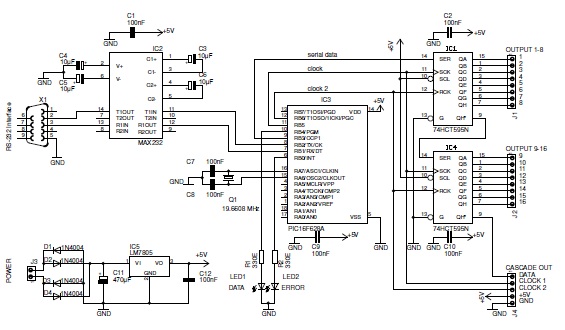
Description: This basic PIC-based RS-232 serial interface can control up to 120 digital TTL outputs.
The described circuit utilizes a PIC microcontroller to facilitate communication via the RS-232 protocol, which is a standard for serial communication. The interface primarily serves to control a maximum of 120 digital TTL (Transistor-Transistor Logic) outputs, enabling the microcontroller to manage multiple devices or components simultaneously.
In this configuration, the PIC microcontroller is programmed to interpret incoming serial data and convert it into corresponding TTL-level signals. The RS-232 standard operates at voltage levels that are not directly compatible with TTL logic, thus a level-shifting circuit may be integrated to ensure proper signal translation between the RS-232 interface and the TTL outputs.
The circuit typically includes a MAX232 or similar level-shifting IC, which converts the RS-232 voltage levels to TTL levels suitable for the PIC microcontroller. The output from the microcontroller can be connected to a series of transistors or relay drivers that control the desired digital outputs. Each output can be independently activated or deactivated based on the commands received via the RS-232 interface.
Additionally, the design may incorporate various protection mechanisms, such as diodes for back EMF protection when driving inductive loads, and resistors to limit current to the outputs. Proper decoupling capacitors should also be used to stabilize the power supply and reduce noise.
Overall, this PIC-based RS-232 serial interface can serve a wide range of applications, from simple control systems to more complex automation tasks, providing a reliable means of communication and control for digital devices.This basic PIC-based RS-232 serial interface can control up to 120 digital TTL outputs..
The described circuit utilizes a PIC microcontroller to facilitate communication via the RS-232 protocol, which is a standard for serial communication. The interface primarily serves to control a maximum of 120 digital TTL (Transistor-Transistor Logic) outputs, enabling the microcontroller to manage multiple devices or components simultaneously.
In this configuration, the PIC microcontroller is programmed to interpret incoming serial data and convert it into corresponding TTL-level signals. The RS-232 standard operates at voltage levels that are not directly compatible with TTL logic, thus a level-shifting circuit may be integrated to ensure proper signal translation between the RS-232 interface and the TTL outputs.
The circuit typically includes a MAX232 or similar level-shifting IC, which converts the RS-232 voltage levels to TTL levels suitable for the PIC microcontroller. The output from the microcontroller can be connected to a series of transistors or relay drivers that control the desired digital outputs. Each output can be independently activated or deactivated based on the commands received via the RS-232 interface.
Additionally, the design may incorporate various protection mechanisms, such as diodes for back EMF protection when driving inductive loads, and resistors to limit current to the outputs. Proper decoupling capacitors should also be used to stabilize the power supply and reduce noise.
Overall, this PIC-based RS-232 serial interface can serve a wide range of applications, from simple control systems to more complex automation tasks, providing a reliable means of communication and control for digital devices.This basic PIC-based RS-232 serial interface can control up to 120 digital TTL outputs..
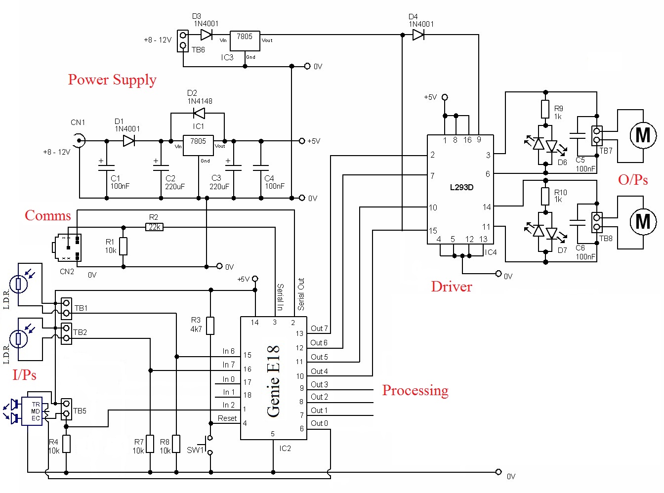
Chosen Circuit
The circuit requires a power source to function. The PIC needs a 5-volt supply, while the driver demands a higher voltage to operate the motors. Inputs: The inputs come from three sensors. Two of these sensors are Light Dependent Resistors...
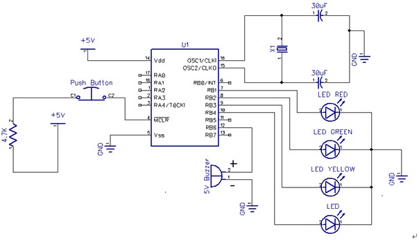
Programming PIC 16F84A
After answering all relevant questions and obtaining the necessary decisions, a thorough study of the PIC datasheet is essential to understand the steps for each configuration and other details. It is important to note that it is bit 3 of...

microcontroller Generate a reset signal from a falling edge trigger
The microcontroller design features the microcontroller (MCU) in hibernation mode, which can only be awakened by a pulse (high-low-high) signal on the reset pin (active low). An accelerometer or an external real-time clock (RTC) serves as the wake-up source. The...
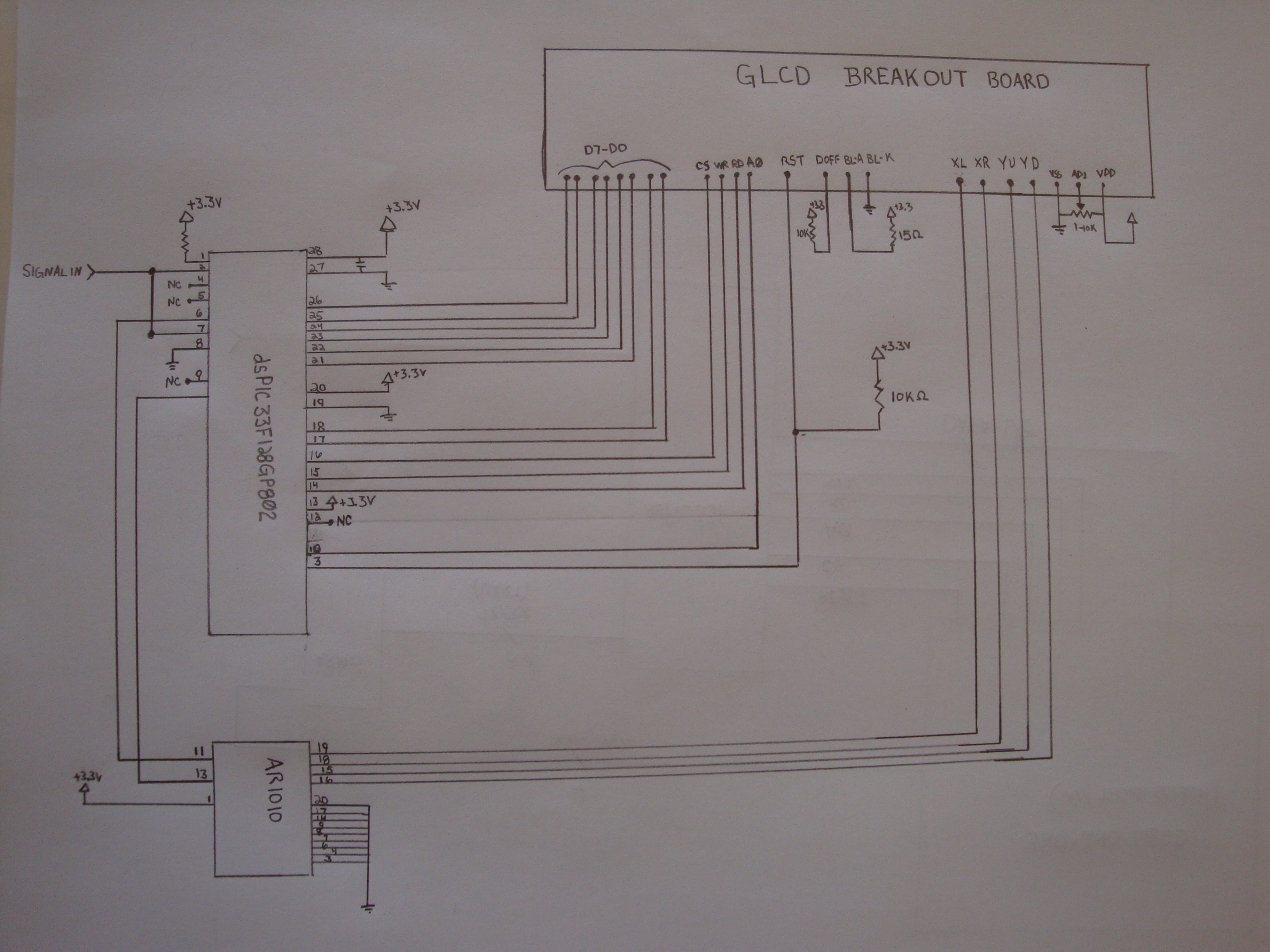
PIC based Oscilliscope
To achieve this project, the initial concept involves sampling an input using an Analog-to-Digital Converter (ADC) at consistent time intervals and subsequently displaying the waveform on a graphic LCD. Adjusting the time scale can be done by modifying the sampling...
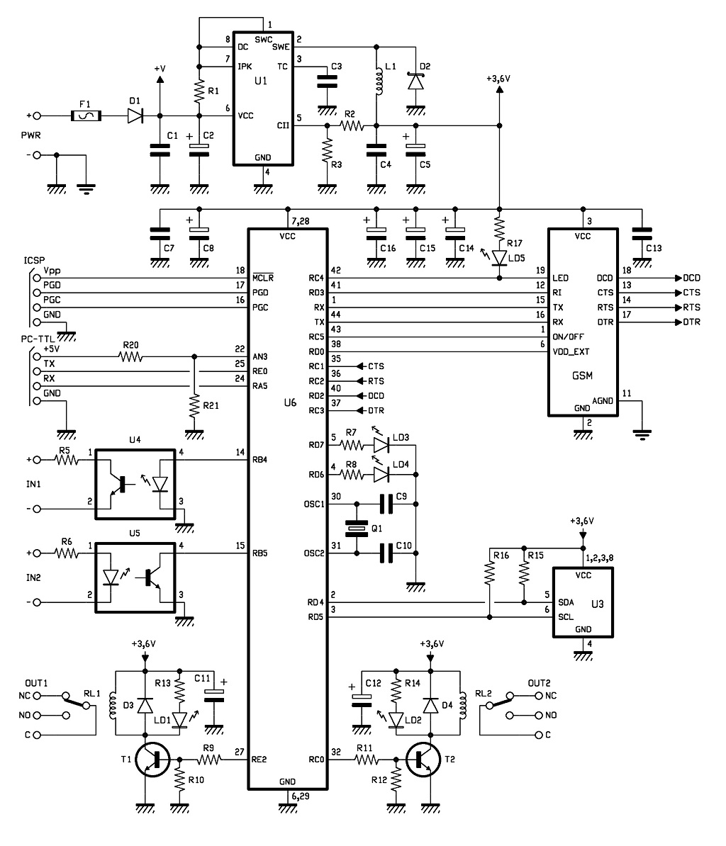
GSM Remote Control 2 IN and 2 OUT Part 2 Schematic
The control of the system is managed by a Microchip PIC18F46K20-I/PT microcontroller, which is programmed with firmware to oversee the activity of the GSM/GPRS module, monitor the logic conditions of two opto-isolated inputs, and send commands to two relays within...
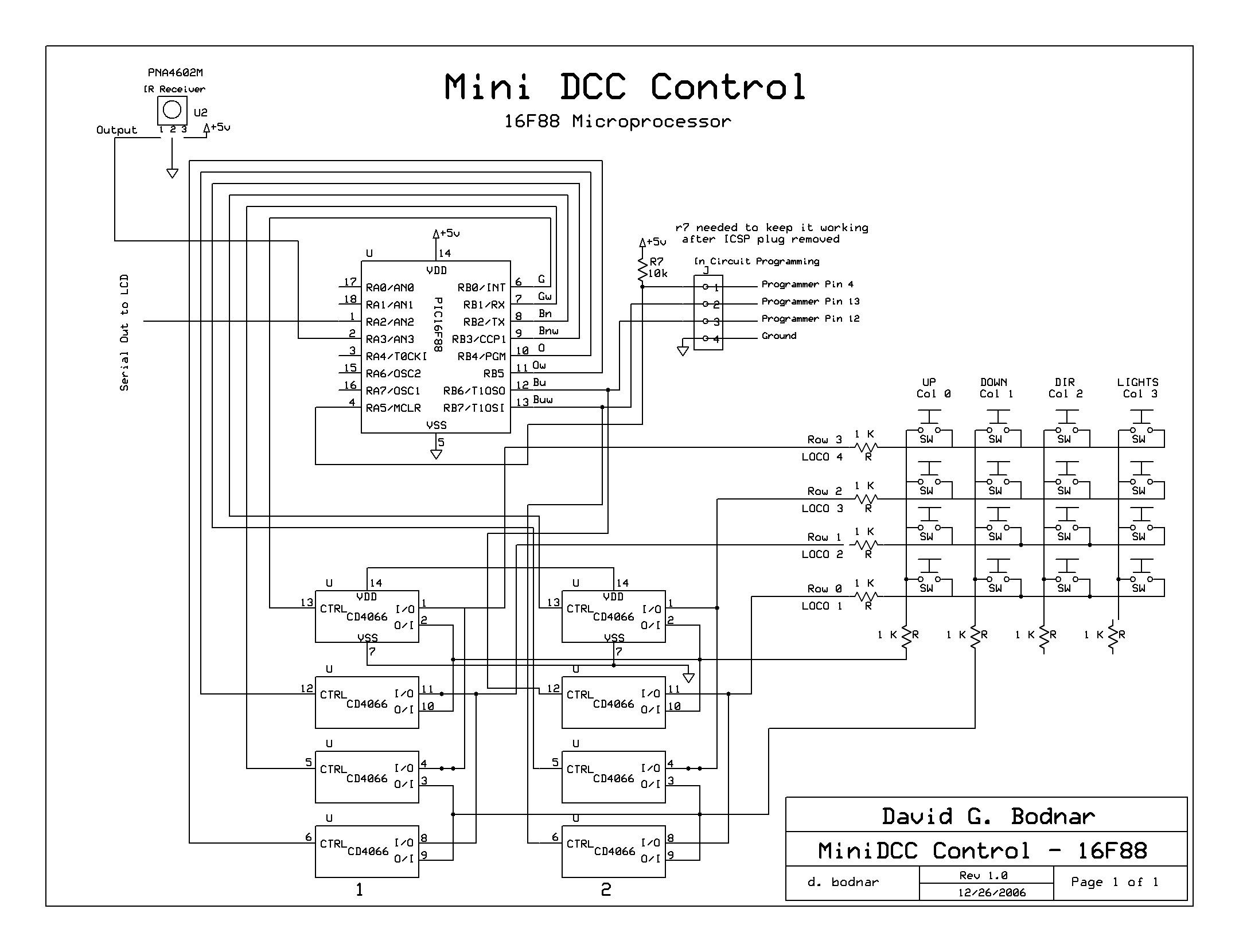
MiniDCC Project
Develop a self-contained unit that can automatically control up to four DCC-equipped engines, starting and stopping them based on their position on a loop of track. The control PIC interacts with the MiniDCC controller through the MiniDCC's keypad. Six pins...
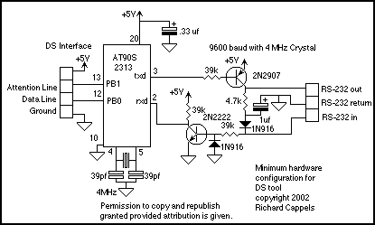
Data Transfer interface
The DS protocol was designed to provide firmware-based bidirectional host-to-slave inter-processor communications for situations in which no hardware solution is available and the host and/or the slave is incapable of tending the interface in real-time. The only specialized hardware required...
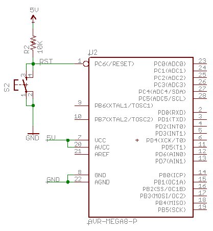
Beginning Embedded Electronics - 2
Acquire all the components required for this lecture here. It is highly recommended to obtain a multimeter with a continuity setting. A quality multimeter with this feature typically costs around $60, while premium models can reach $300. The $60 option...
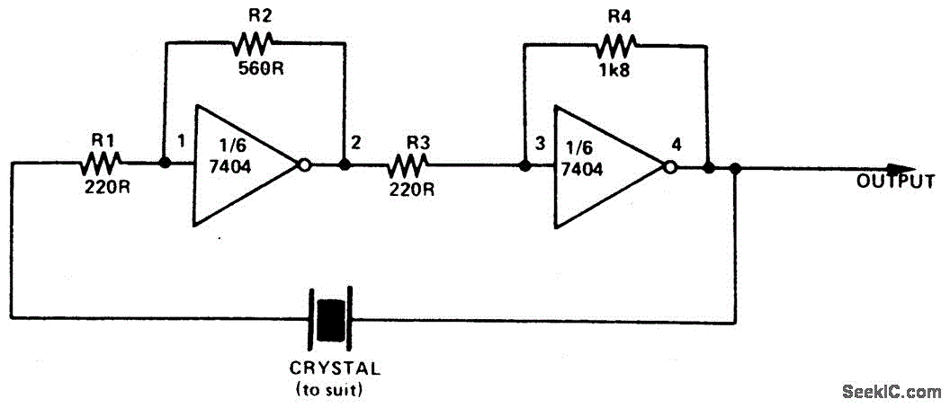
SIMPLE TTL CRYSTAL OSCILLATOR
This simple and inexpensive crystal oscillator consists of one-third of a 7404 hex inverter, four resistors, and a crystal. The inverters are biased into their linear regions by resistors R1 to R4, while the crystal provides the necessary feedback. Oscillation...