


Connect Nokia 3310 LCD to LPT port
#Nokia 3310 LCD
#LPT port
#graphical LCD
#PC interface
#voltage reduction
#diodes
#simple circuit
#display driver
#parallel port
#retro computing
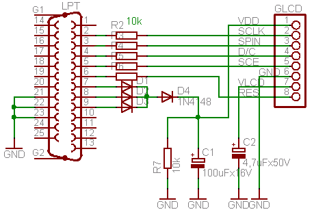
Description: This circuit is designed to drive a Nokia 3310 graphical LCD using a simple LPT cable and associated PC software. The graphical LCD requires a supply voltage of approximately 3.3V, while the LPT port provides a voltage range of about 4.5V to 5V. To reduce the voltage appropriately, diodes are employed, which drop the voltage according to the formula: 4.5V - 0.7V - 0.7V = 3.1V. Once the hardware setup is complete, images can be drawn on the LCD. A control program is available for download, including Pascal source code. The software is designed to operate directly with ports in DOS or Windows 98. For users of Windows 2000 or XP, it is recommended to read about accessing LPT and COM ports under Windows NT/2000/XP. The PortTalk utility should be downloaded and extracted to a separate folder. The file "allowio.exe" must be copied to the directory containing the program intended for execution. A shortcut for the compiled program, such as LCD.exe, should be created, and the target line in the file properties should be modified accordingly.
This circuit utilizes a Nokia 3310 graphical LCD, which is a compact and efficient display option commonly used in various electronic projects. The LPT (Line Printer Terminal) port serves as the communication interface between the computer and the LCD. The voltage level adjustment is crucial, as the LCD operates at a lower voltage than what the LPT port supplies. The inclusion of diodes in the circuit is a practical solution for voltage reduction; standard silicon diodes can be used to achieve the necessary voltage drop.
The schematic for this circuit should illustrate the connection points between the LPT port and the LCD. The LPT port typically has multiple pins, and the specific pins used will depend on the programming and data transmission requirements. The diodes should be placed in series with the power line to the LCD to ensure that the voltage does not exceed its maximum rating.
Once the hardware is assembled, the next step involves software configuration. The provided control program is essential for sending the appropriate signals to the LCD. The software must be compatible with the operating system in use; thus, users on Windows 2000 or XP should follow the guidelines for utilizing PortTalk, which facilitates direct access to the hardware ports.
To set up the software, after copying "allowio.exe" to the program directory, users should create a shortcut for the executable file (e.g., LCD.exe). Modifying the target line in the properties of this shortcut is necessary to ensure that the program runs with the required permissions to access the LPT port.
Overall, this circuit is an excellent example of interfacing legacy hardware with modern computing systems, showcasing both the simplicity and effectiveness of using basic electronic components and programming techniques to achieve desired functionality.I found this circuit really simple and interesting. It is really simple to drive Nokia 3310 graphical LCD by using simple LPT cable and some PC software. Firs of all connect graphical LCD to LPT port according to following circuit: Graphical display needs about 3.
3V of supply voltage, while LPT gives about 4. 5 -5V. This is why diodes are used to r educe voltage by formula: 4. 5V-0. 7V-0. 7V=3. 1V. When hardware part is done it is time to draw some images on LCD. For this download control program (Pascal source is included in package too). Software is written to drive ports directly in DOS or win98 operating system. If you are using Win2000 or XP you might want to read: Program LPT and COM ports easily under windows NT-2000-XP. Download PortTalk and unzip it in separate folder somewhere. Then copyallowio. exedirectly to the directory where is you program which you want to run. Then create shortcut of your compiled program for instance LCD. exe. Then open files properties and in line target do following changes:
This circuit utilizes a Nokia 3310 graphical LCD, which is a compact and efficient display option commonly used in various electronic projects. The LPT (Line Printer Terminal) port serves as the communication interface between the computer and the LCD. The voltage level adjustment is crucial, as the LCD operates at a lower voltage than what the LPT port supplies. The inclusion of diodes in the circuit is a practical solution for voltage reduction; standard silicon diodes can be used to achieve the necessary voltage drop.
The schematic for this circuit should illustrate the connection points between the LPT port and the LCD. The LPT port typically has multiple pins, and the specific pins used will depend on the programming and data transmission requirements. The diodes should be placed in series with the power line to the LCD to ensure that the voltage does not exceed its maximum rating.
Once the hardware is assembled, the next step involves software configuration. The provided control program is essential for sending the appropriate signals to the LCD. The software must be compatible with the operating system in use; thus, users on Windows 2000 or XP should follow the guidelines for utilizing PortTalk, which facilitates direct access to the hardware ports.
To set up the software, after copying "allowio.exe" to the program directory, users should create a shortcut for the executable file (e.g., LCD.exe). Modifying the target line in the properties of this shortcut is necessary to ensure that the program runs with the required permissions to access the LPT port.
Overall, this circuit is an excellent example of interfacing legacy hardware with modern computing systems, showcasing both the simplicity and effectiveness of using basic electronic components and programming techniques to achieve desired functionality.I found this circuit really simple and interesting. It is really simple to drive Nokia 3310 graphical LCD by using simple LPT cable and some PC software. Firs of all connect graphical LCD to LPT port according to following circuit: Graphical display needs about 3.
3V of supply voltage, while LPT gives about 4. 5 -5V. This is why diodes are used to r educe voltage by formula: 4. 5V-0. 7V-0. 7V=3. 1V. When hardware part is done it is time to draw some images on LCD. For this download control program (Pascal source is included in package too). Software is written to drive ports directly in DOS or win98 operating system. If you are using Win2000 or XP you might want to read: Program LPT and COM ports easily under windows NT-2000-XP. Download PortTalk and unzip it in separate folder somewhere. Then copyallowio. exedirectly to the directory where is you program which you want to run. Then create shortcut of your compiled program for instance LCD. exe. Then open files properties and in line target do following changes:

Display Driver circuit
This display driver circuit illustrates how a Seven Segment Display is driven using the 5-stage Johnson decade counter IC CD4033. The integrated circuit functions as a counter.
The CD4033 is a versatile decade counter that can be utilized to drive a...
Uplifter Switches
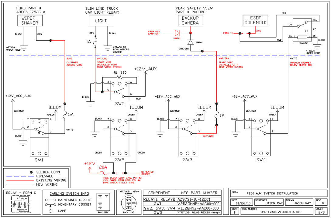
A +12V switched wire was routed back to the camera wiring and connected at the same point as the reverse lights. This configuration allows either the reverse lights or the switch to activate the camera. The critical component in this...
Whats the purpose of the diodes in this circuit
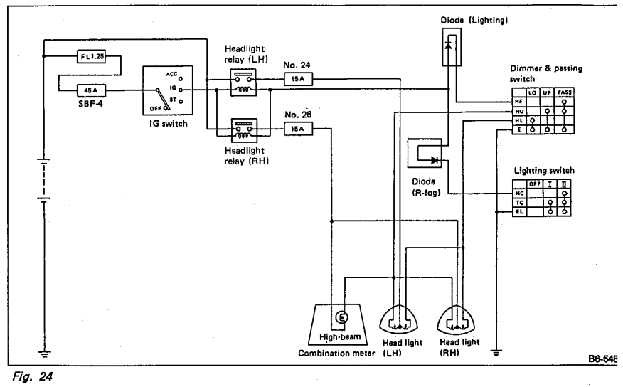
Understanding the headlight wiring in a car involves examining the purpose of two diodes in the circuit diagram. The circuit allows for two independent methods of activating the light relays: through the light switch or by flashing the high beams....
Design Parallel Port Interface Project PCB
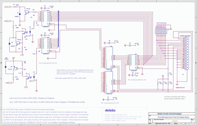
The following schematic illustrates the design of a Parallel Port Interface Circuit Diagram utilizing the 74HCT373. The 74HC/HCT373 are high-speed silicon-gate CMOS devices that are pin-compatible with low-power Schottky TTL (LSTTL). This parallel port interface circuit can drive 256 relays...
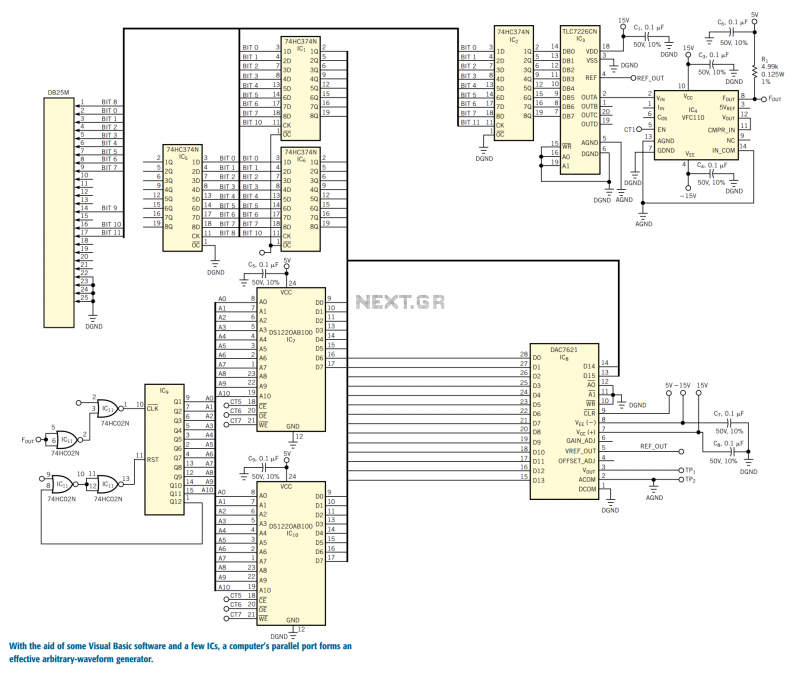
Parallel port controls arbitrary-waveform generator
You can use the parallel port of your PC and a few additional components to generate a powerful, easy-to-use arbitrary-waveform generator. By using a Visual Basic program with the circuit in Figure 1, you can generate any waveform (for example,...
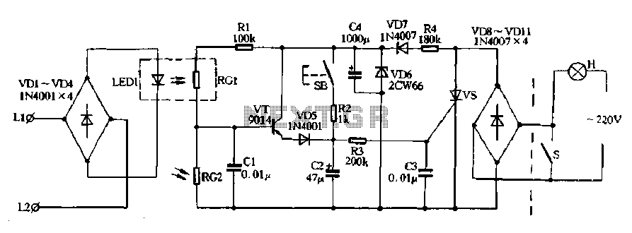
Automatic lighting control telephone signals
Diodes VD8 to VDI1 function as part of the main circuit isolation, with SCR serving as a composition control switch. The buck regulator circuit is composed of a stable orbital tube VD6 and a simple resistor-capacitor combination (C4). The circuit...
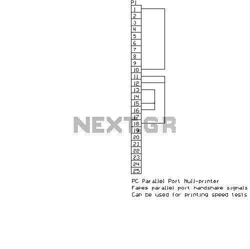
PC parallel port Null Printer Adapter
This circuit is a simple adapter for PC parallel port to think that there is a printer connected to computer. This adapter is useful for testing printing speed with different software and as a part of your own designs. You...
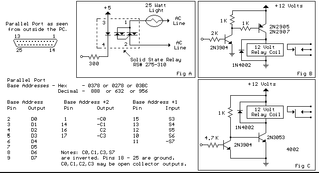
Parallel Port Interface with relay
Below are three examples of controlling a relay from the PC's parallel printer port (LPT1 or LPT2). Figure A shows a solid state relay controlled by one of the parallel port data lines (D0-D7) using a 300 ohm resistor and...
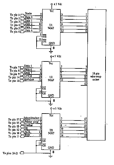
Simple Parallel (Printer) Port Interface
This is the basic interface I used as part of my Computerized Room project. This is the parallel interface only. The 8 bit input card can be found, along with the rest of the project, at Computerize Your Room/House. This...