


High speed paper tape reader
#optical reader
#paper tape
#logic signal
#photodarlington
#high speed
#computer peripheral
#interface
#sensor
#low cost
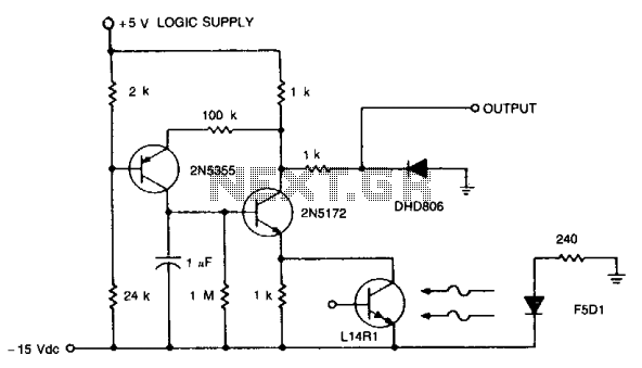
Description: When interfacing computer peripheral equipment, it is advantageous to utilize logic signal levels. This circuit operates with a nominal output of 4 V, which drops to -0.6 V upon illumination, meeting the specifications for a high-speed optical reader system for paper tape. The circuit can function at speeds of up to 1000 bits per second and is designed to operate with tape translucency that allows 50% of the incident light to reach the sensor. It provides a fixed threshold signal to the logic circuit while maintaining low costs. Several techniques are employed in the design. The speed of the photodarlington is enhanced through cascode constant voltage biasing.
The output threshold and tape translucency requirements are met by monitoring the output voltage and enabling operation at 2000 bits per second under ambient light levels equivalent to signal levels.
The described circuit is structured to facilitate the reliable interfacing of peripheral devices through the use of logic signal levels, which are essential for digital communication. The nominal output voltage of 4 V signifies a logic high state, while the drop to -0.6 V indicates a logic low state when the optical sensor is illuminated by the tape. This behavior is crucial for accurately reading data from high-speed paper tape optical readers.
Operating at speeds up to 1000 bits per second allows for efficient data transmission, while the capability to handle tape translucency that transmits 50% of incident light ensures versatility in various lighting conditions. The design emphasizes cost-effectiveness without compromising performance, making it suitable for applications where budget constraints are a consideration.
The implementation of cascode constant voltage biasing serves to enhance the response time of the photodarlington transistor, thereby improving the overall speed and efficiency of the optical reading process. This configuration minimizes the effects of voltage variations and optimizes the sensor's performance, ensuring that it reliably detects the light signals corresponding to the data encoded on the tape.
Moreover, the ability to operate at 2000 bits per second under ambient light levels comparable to signal levels indicates that the circuit is robust against noise and fluctuations in the environment. By continuously monitoring the output voltage, the circuit can dynamically adjust to maintain the required threshold for accurate data interpretation. This adaptability is particularly beneficial in real-world applications where lighting conditions may vary significantly.
In summary, this circuit design not only meets the fundamental requirements for interfacing with computer peripherals but also incorporates advanced techniques to enhance performance, making it a reliable solution for high-speed optical reading applications.When computer peripheral equipment is interfaced, it is convenient to work with logic signal levels. With a nominal 4 V at the output dropping to - 0.6 V on illumination, this circuit reflects the requirements of a high-speed, paper tape optical reader system. The circuit operates at rates of up to 1000 bits per second. It will also operate at tape translucency such that 50% of the incident light is transmitted to the sensor, and provide a fixed threshold signal to the logic circuit, all at low cost.
Several circuit tricks are required. Photodarlington speed is enhanced by cascode constant voltage biasing. The output threshold and tape translucency requirements are provided for by sensing the output voltage and operating to 2000 bits per second at ambient light levels equal to signal levels.
The output threshold and tape translucency requirements are met by monitoring the output voltage and enabling operation at 2000 bits per second under ambient light levels equivalent to signal levels.
The described circuit is structured to facilitate the reliable interfacing of peripheral devices through the use of logic signal levels, which are essential for digital communication. The nominal output voltage of 4 V signifies a logic high state, while the drop to -0.6 V indicates a logic low state when the optical sensor is illuminated by the tape. This behavior is crucial for accurately reading data from high-speed paper tape optical readers.
Operating at speeds up to 1000 bits per second allows for efficient data transmission, while the capability to handle tape translucency that transmits 50% of incident light ensures versatility in various lighting conditions. The design emphasizes cost-effectiveness without compromising performance, making it suitable for applications where budget constraints are a consideration.
The implementation of cascode constant voltage biasing serves to enhance the response time of the photodarlington transistor, thereby improving the overall speed and efficiency of the optical reading process. This configuration minimizes the effects of voltage variations and optimizes the sensor's performance, ensuring that it reliably detects the light signals corresponding to the data encoded on the tape.
Moreover, the ability to operate at 2000 bits per second under ambient light levels comparable to signal levels indicates that the circuit is robust against noise and fluctuations in the environment. By continuously monitoring the output voltage, the circuit can dynamically adjust to maintain the required threshold for accurate data interpretation. This adaptability is particularly beneficial in real-world applications where lighting conditions may vary significantly.
In summary, this circuit design not only meets the fundamental requirements for interfacing with computer peripherals but also incorporates advanced techniques to enhance performance, making it a reliable solution for high-speed optical reading applications.When computer peripheral equipment is interfaced, it is convenient to work with logic signal levels. With a nominal 4 V at the output dropping to - 0.6 V on illumination, this circuit reflects the requirements of a high-speed, paper tape optical reader system. The circuit operates at rates of up to 1000 bits per second. It will also operate at tape translucency such that 50% of the incident light is transmitted to the sensor, and provide a fixed threshold signal to the logic circuit, all at low cost.
Several circuit tricks are required. Photodarlington speed is enhanced by cascode constant voltage biasing. The output threshold and tape translucency requirements are provided for by sensing the output voltage and operating to 2000 bits per second at ambient light levels equal to signal levels.
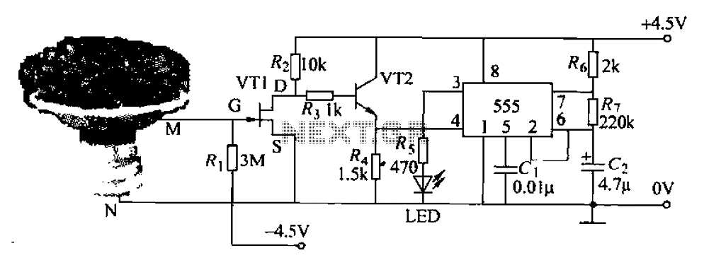
Pots water alarm circuit
The flowers in pots require watering, as relying solely on the observation of moist soil surfaces can be unreliable. To address this issue, a flower watering indicator has been developed. This circuit includes a field effect transistor (VT1), a second...
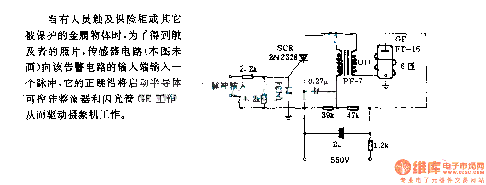
The alarm circuit diagram for safety box and other metal objects
When an individual touches the safety box or other protected metal objects, the sensor circuit generates a pulse to the alarm circuit. The positive edge of this pulse activates the semiconductor and thyristor flash GE, subsequently triggering the camera to...
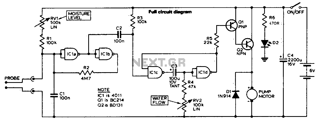
Automatic plant waterer
The unit consists of a sensor, timer, and electric water pump. The sensor is embedded in the soil, and when dry, the electronics operate the water pump for a preset time. The circuit is composed of a level-sensitive Schmitt trigger,...
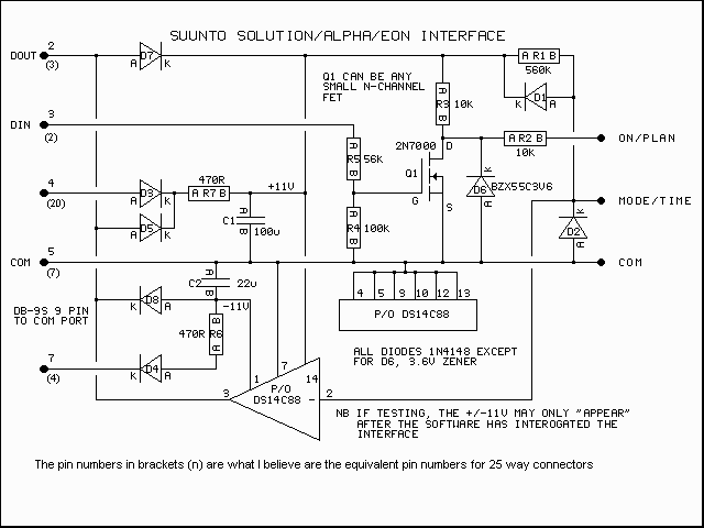
Suunto PC Interface
This page contains GIF images of the circuit diagram for the Solution interface, the PCB artwork, the board layout, a typical side elevation of the assembly, a parts list, some hints, and a brief overview of troubleshooting. This is a...
The alarm circuit diagram for safety box and other metal objects
When an individual touches the safety box or other protected metal objects, the sensor circuit generates a pulse to the alarm circuit. The positive edge of this pulse activates the semiconductor and thyristor flash GE, subsequently triggering the camera to...
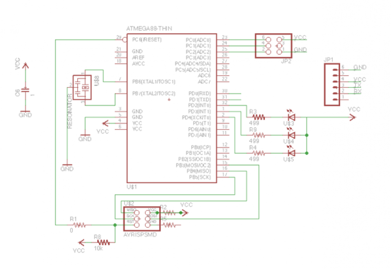
Add a sensor to a board and measure something with it
This week's plan is to build a device that warns of the potential for a knockdown, which is the process by which an over-canvassed ship is laid over on her beam-ends. The risk of sinking is high during this event,...
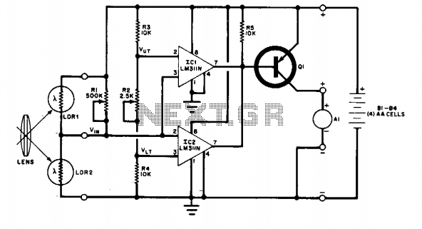
Field disturbance sensor-alarm
The change in ambient light triggers the alarm by changing the resistance of LDR1 and LDR2.
The circuit utilizes two light-dependent resistors (LDR1 and LDR2) to detect variations in ambient light levels. LDRs are passive components that exhibit a change in...
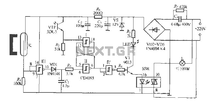
Gate automatic lamp circuit
The circuit utilizes multiple integrated circuits to form an automatic lighting device that is activated by door and window sensors. It includes CD4093 digital integrated circuits, a relay, and a power supply circuit. The system typically remains closed when a...
Aladin
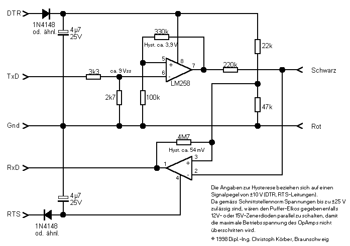
Whoever thinks about reproducing an interface for the Aladin should first of all be aware of the fact that there are two different versions of the interface. The first version, easier to assemble, enables the user to transfer dive data...