


Interface between Ericsson 6xx/7xx phones and a PC
#RS232
#TTL
#MAX232
#serial port
#Ericsson phones
#PC interface
#voltage level converter
#system connector
#communication protocol
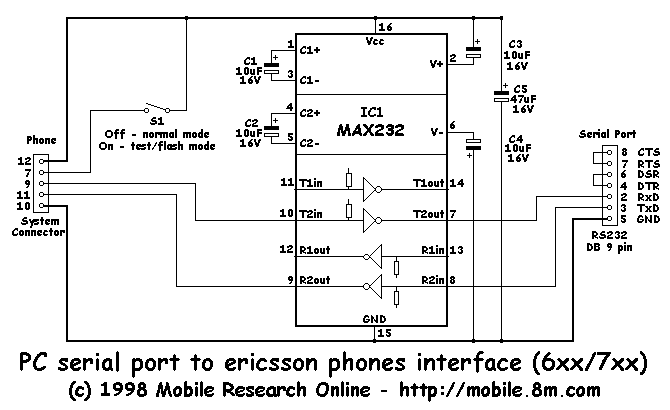
Description: This interface is needed to connect the phone to a PC, because the PC's serial port works with voltage levels between -12 and 12V (RS232 protocol) and the phone operates between 0 and 5V (TTL protocol). Don't even think of connecting your phone directly to the serial port; this would certainly damage your phone and/or the PC serial port! The interface's main component is IC1 - MAX232, a common IC in RS232 - TTL interfaces, with some external components which are needed for the IC to work correctly. The main difference between this and other interfaces is the S1 switch and the phone System Connector. To get more info about the System connector, like pin-out, go to the pin-out page.
The described interface serves as a crucial bridge between devices operating on different voltage levels and communication protocols. The MAX232 integrated circuit is specifically designed to convert signals from TTL (Transistor-Transistor Logic) levels, which range from 0 to 5 volts, to RS232 levels, which can vary from -12 to +12 volts. This conversion is essential for ensuring compatibility between the phone and the PC's serial port, preventing potential damage that could arise from direct connection.
The circuit typically includes the MAX232 IC, which requires a few external components for proper operation, including capacitors that help in voltage conversion and regulation. The MAX232 uses a charge pump to generate the necessary negative voltage for RS232 communication. Commonly, this involves four external capacitors (usually 1µF) connected to specific pins of the IC to facilitate the charge pumping process.
The S1 switch serves a dual purpose in this interface. It can be used to toggle between different operational modes or to enable/disable the connection to the phone, providing flexibility in usage. The phone System Connector is specifically designed to interface with the phone's communication port, and its pin configuration must be adhered to for proper connectivity and functionality. For detailed pin-out information, consulting the pin-out page is essential to ensure correct wiring and avoid misconnection.
Overall, this interface is a practical solution for connecting a phone to a PC while ensuring that both devices operate within their respective voltage and signal requirements, thus maintaining the integrity and functionality of both devices.This interface is needed to connect the phone to a PC, because the PC`s serial port works with voltage levels between -12 and 12V (RS232 protocol) and the phone operates between 0 and 5V (TTL protocol). Don`t even think in conecting your phone directly to the serial port, this would certainly damage your phone and/or the PC serial port!!!
The interface main component is IC1 - MAX232, a common IC in RS232 - TTL interfaces, with some external components wich are needed for the IC to work correctly. The main difference between this and other interfaces is the S1 switch and the phone System Connector.
To get more info about the System connector, like pin.out, go to the pin-out page.
The described interface serves as a crucial bridge between devices operating on different voltage levels and communication protocols. The MAX232 integrated circuit is specifically designed to convert signals from TTL (Transistor-Transistor Logic) levels, which range from 0 to 5 volts, to RS232 levels, which can vary from -12 to +12 volts. This conversion is essential for ensuring compatibility between the phone and the PC's serial port, preventing potential damage that could arise from direct connection.
The circuit typically includes the MAX232 IC, which requires a few external components for proper operation, including capacitors that help in voltage conversion and regulation. The MAX232 uses a charge pump to generate the necessary negative voltage for RS232 communication. Commonly, this involves four external capacitors (usually 1µF) connected to specific pins of the IC to facilitate the charge pumping process.
The S1 switch serves a dual purpose in this interface. It can be used to toggle between different operational modes or to enable/disable the connection to the phone, providing flexibility in usage. The phone System Connector is specifically designed to interface with the phone's communication port, and its pin configuration must be adhered to for proper connectivity and functionality. For detailed pin-out information, consulting the pin-out page is essential to ensure correct wiring and avoid misconnection.
Overall, this interface is a practical solution for connecting a phone to a PC while ensuring that both devices operate within their respective voltage and signal requirements, thus maintaining the integrity and functionality of both devices.This interface is needed to connect the phone to a PC, because the PC`s serial port works with voltage levels between -12 and 12V (RS232 protocol) and the phone operates between 0 and 5V (TTL protocol). Don`t even think in conecting your phone directly to the serial port, this would certainly damage your phone and/or the PC serial port!!!
The interface main component is IC1 - MAX232, a common IC in RS232 - TTL interfaces, with some external components wich are needed for the IC to work correctly. The main difference between this and other interfaces is the S1 switch and the phone System Connector.
To get more info about the System connector, like pin.out, go to the pin-out page.
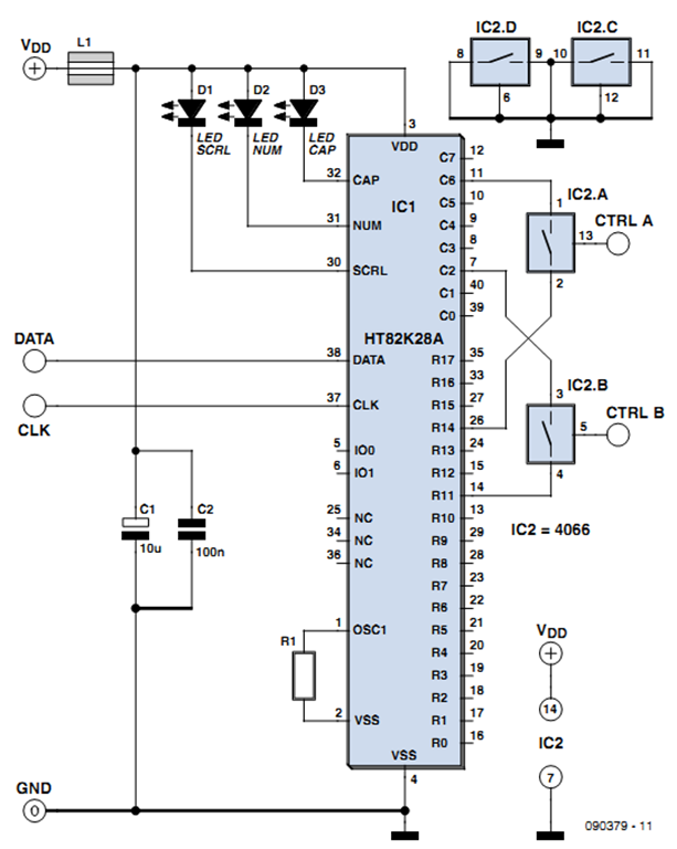
control interface via pc keyboard
One of the more challenging aspects of creating a control or security system that utilizes a PC, such as a burglar alarm, is connecting the sensors to the computer. This typically requires specialized interface expansion boards, and programming that includes...
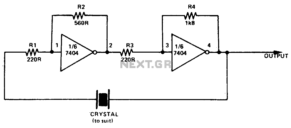
Simple ttl crystal oscillator
This simple and inexpensive crystal oscillator consists of one-third of a 7404 IC, four resistors, and a crystal. The inverters are biased into their linear regions by resistors R1 to R4, while the crystal provides the necessary feedback. Oscillation can...
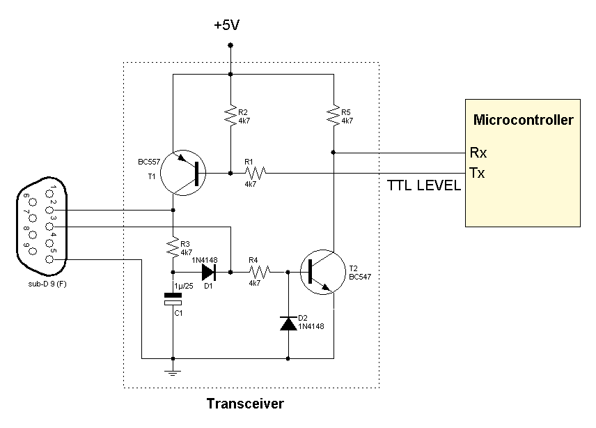
RS232 transceiver circuits
Several RS232 transceiver circuits are used for communication between microcontrollers and other devices, such as PCs or RS232 devices. This document presents a collection of well-known RS232 transceiver circuits. The circuit utilizes the MAX232 from Maxim's devices, which is recognized...
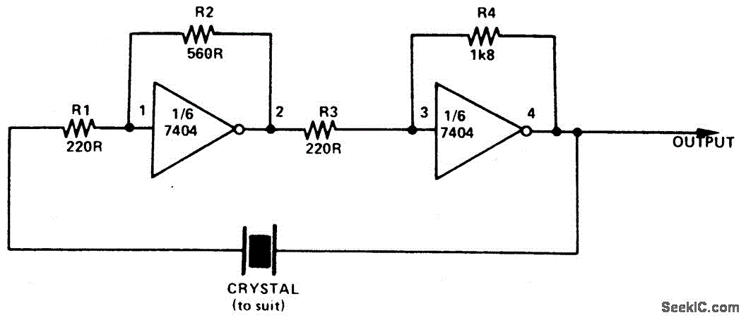
SIMPLE TTL CRYSTAL OSCILLATOR
This simple and inexpensive crystal oscillator consists of one-third of a 7404 hex inverter, four resistors, and a crystal. The inverters are biased into their linear regions by resistors R1 to R4, while the crystal provides the necessary feedback. Oscillation...

Schematics of TTL CPU
The third Eagle layout of the program counter has been completed, presenting a clearer design compared to the previous iterations, which were cluttered with intersecting wires, making it difficult to discern connections. This diagram is intended to facilitate understanding of...

TTL signal levels using a serial port MAX232
A PC’s serial port provides signal lines that you can use to expand the number of input signals. With some additional circuitry tied to these lines, you can use the port to test digital TTL logic-level circuits. You just need...
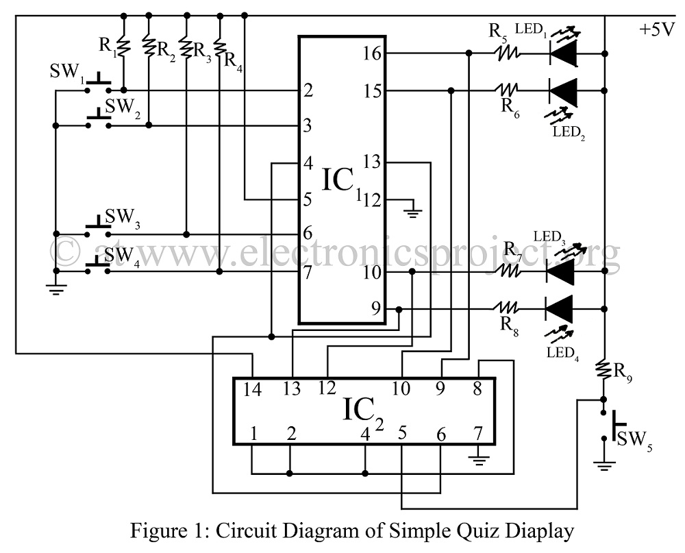
Simple Quiz Display
A simple quiz display is constructed using two TTL ICs: the 7445 and the 7420. It indicates which switch is pressed first, accompanied by a circuit diagram. This project represents an interesting and verified game concept.
The circuit utilizes the TTL...
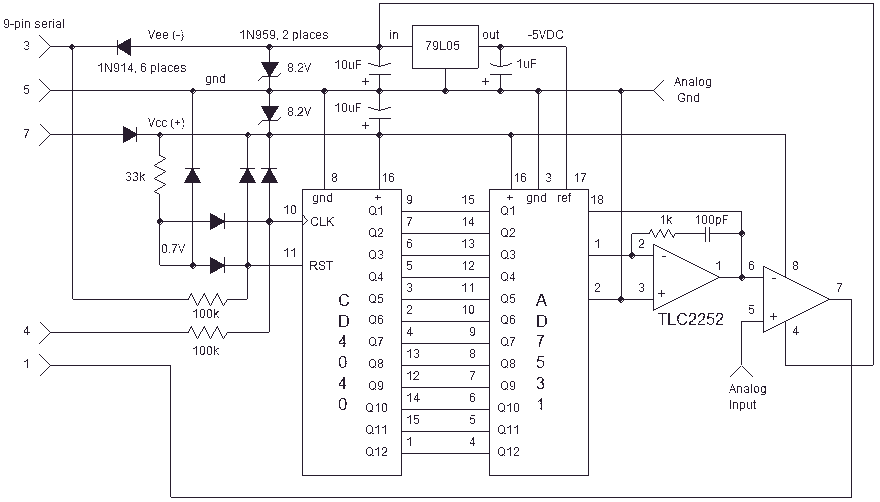
Computer Serial Port interface
Here is an inexpensive way to get slow-moving analog data directly into a spreadsheet on your computer! A simple circuit connects to a serial port and a short Qbasic program gathers and saves 12 bit data to a file. A...
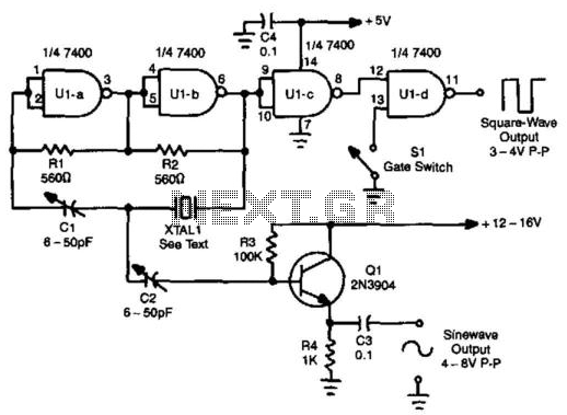
Sine- And Square-Wave Ttl Oscillator
A TTL oscillator utilizing a Quad NAND Gate can operate with fundamental crystals ranging from 1 to 10 MHz. The sine wave output is derived directly from the crystal, which functions as its own filter, producing a relatively clean sine...