


PIXpand (beta 0.1)
#TI calculator
#Playstation
#memory cards
#data storage
#beta release
#testing
#interface
#electronics project
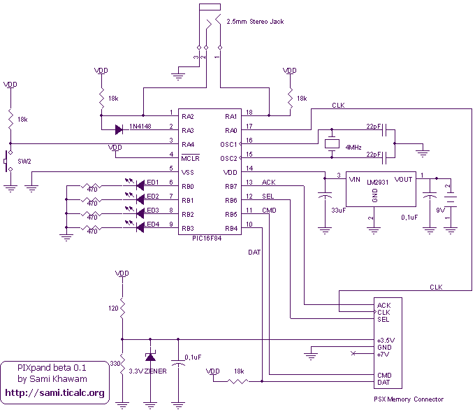
Description: This is a beta release of the PIXpand project. The PIXpand is a device that connects to a TI calculator and enables it to store and retrieve data to and from PlayStation memory cards. A beta release has been made as there is currently no time to continue with the project. Feedback on the device's functionality and bug testing is encouraged.
The PIXpand project involves the design of a device that serves as an interface between Texas Instruments (TI) calculators and PlayStation memory cards. The primary function of the PIXpand is to facilitate data storage and retrieval, allowing users to transfer information between these two platforms.
The circuit design of the PIXpand includes several key components. A microcontroller serves as the central processing unit, managing communication between the TI calculator and the memory card. The microcontroller is programmed to interpret commands from the calculator and convert them into a format compatible with the memory card's data structure.
Power management is crucial in this design, as both the TI calculator and the PlayStation memory card operate at different voltage levels. A voltage regulator may be incorporated to ensure that the microcontroller and other components receive stable power. Additionally, level shifters could be necessary to adapt the signal levels between the two devices, preventing damage and ensuring reliable communication.
The communication protocol between the TI calculator and the PIXpand can be established using serial communication, typically through UART (Universal Asynchronous Receiver-Transmitter) or I2C (Inter-Integrated Circuit). The choice of protocol will depend on the specific requirements of the TI calculator and the desired data transfer speed.
The memory card interface will also require careful consideration. The design must accommodate the specific pinout and signaling requirements of the PlayStation memory card. This may involve using a dedicated memory card interface chip or implementing the necessary logic in the microcontroller firmware.
In terms of physical design, the PIXpand device should be compact and portable, allowing easy connection to the TI calculator. A custom PCB (Printed Circuit Board) could be designed to house the microcontroller, voltage regulators, level shifters, and any additional components, ensuring a neat and efficient layout.
Testing and debugging will be critical phases in the development of the PIXpand. Users are encouraged to provide feedback on performance, including data transfer rates, reliability, and any issues encountered during operation. This information will be invaluable for further development and refinement of the device.This is a beta release of the PIXpand project. The PIXpand which is a device that connects to a TI calculator and enable it to store and retreive data to and from Playstation Memory cards. I am making this beta release as I do not have the time to continue with the project right now. Thus I would be grateful if people can build this device and test it to see how well it work and to check for any bugs.
The PIXpand project involves the design of a device that serves as an interface between Texas Instruments (TI) calculators and PlayStation memory cards. The primary function of the PIXpand is to facilitate data storage and retrieval, allowing users to transfer information between these two platforms.
The circuit design of the PIXpand includes several key components. A microcontroller serves as the central processing unit, managing communication between the TI calculator and the memory card. The microcontroller is programmed to interpret commands from the calculator and convert them into a format compatible with the memory card's data structure.
Power management is crucial in this design, as both the TI calculator and the PlayStation memory card operate at different voltage levels. A voltage regulator may be incorporated to ensure that the microcontroller and other components receive stable power. Additionally, level shifters could be necessary to adapt the signal levels between the two devices, preventing damage and ensuring reliable communication.
The communication protocol between the TI calculator and the PIXpand can be established using serial communication, typically through UART (Universal Asynchronous Receiver-Transmitter) or I2C (Inter-Integrated Circuit). The choice of protocol will depend on the specific requirements of the TI calculator and the desired data transfer speed.
The memory card interface will also require careful consideration. The design must accommodate the specific pinout and signaling requirements of the PlayStation memory card. This may involve using a dedicated memory card interface chip or implementing the necessary logic in the microcontroller firmware.
In terms of physical design, the PIXpand device should be compact and portable, allowing easy connection to the TI calculator. A custom PCB (Printed Circuit Board) could be designed to house the microcontroller, voltage regulators, level shifters, and any additional components, ensuring a neat and efficient layout.
Testing and debugging will be critical phases in the development of the PIXpand. Users are encouraged to provide feedback on performance, including data transfer rates, reliability, and any issues encountered during operation. This information will be invaluable for further development and refinement of the device.This is a beta release of the PIXpand project. The PIXpand which is a device that connects to a TI calculator and enable it to store and retreive data to and from Playstation Memory cards. I am making this beta release as I do not have the time to continue with the project right now. Thus I would be grateful if people can build this device and test it to see how well it work and to check for any bugs.
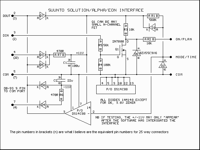
Suunto PC Interface
This page contains GIF images of the circuit diagram for the Solution interface, the PCB artwork, the board layout, a typical side elevation of the assembly, a parts list, some hints, and a brief overview of troubleshooting. This is a...
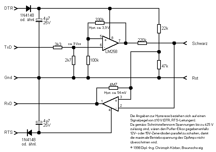
Aladin
Whoever thinks about reproducing an interface for the Aladin should first of all be aware of the fact that there are two different versions of the interface. The first version, easier to assemble, enables the user to transfer dive data...
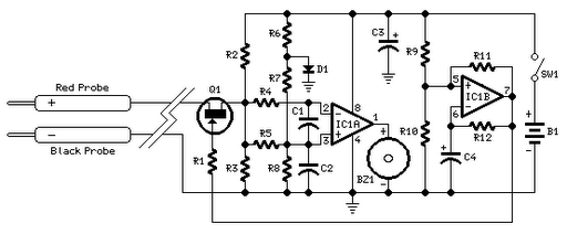
Quick On-Board Junction TesterCircuit
Short circuits or broken PCB tracks can be easily identified using a multimeter; however, this tool may yield inaccurate results when testing the efficiency of a transistor or diode unless the component is unsoldered and removed from the PCB. Another...
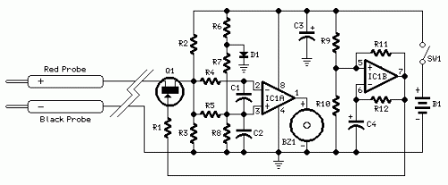
Quick On-Board Junction Tester
Short circuits or broken PCB tracks can be easily identified using a multimeter. However, this tool may yield inaccurate results when assessing the efficiency of a transistor or diode unless the component is unsoldered and removed from the PCB. Additionally,...
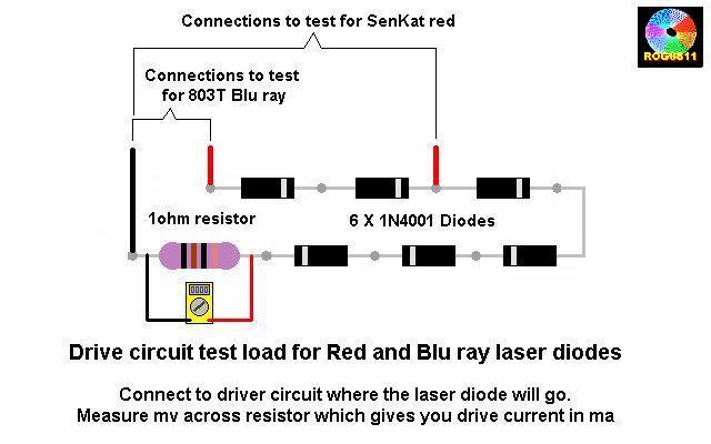
testing ddl s circuit
A guide will be posted on how to test a DDL circuit before integrating the LD. The process aims to ensure clarity and accuracy throughout.
To properly test a DDL (Direct Drive Laser) circuit before adding the LD (Laser Diode), several...