


port jtag cable buffered
#JTAG
#buffered cable
#Wiggler cable
#debugging
#hardware interface
#Macraigor Systems
#schematic
#electronics
#programming
#embedded systems
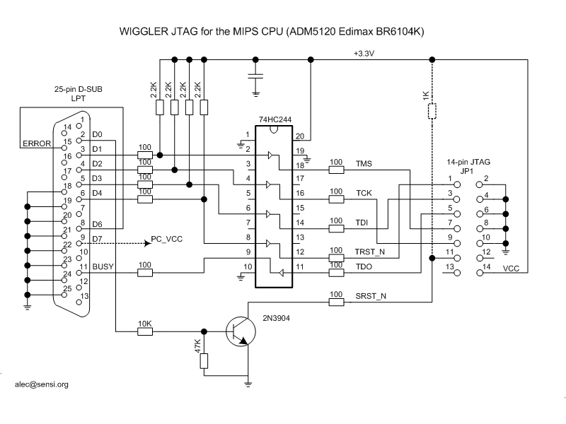
Description: This type of cable is more complex than the unbuffered variant, yet it is still relatively easy to construct. The most commonly used cable in this category is the Wiggler cable, which is commercially available from Macraigor Systems. Priced at $150 USD, it is considered expensive. A widely accepted schematic available online is believed to represent the internal configuration of a Wiggler cable. This schematic, created by Alec, is designed for devices that utilize a typical EJTAG header, specifically for those based on the ADM5120 System-on-Chip, which follows the MIPS32 architecture. The ADM5120 supports EJTAG v2.6, which does not facilitate DMA transfers. While an unbuffered cable can be constructed for approximately $5 USD or less, the components for a Wiggler-type cable typically cost between $15 to $30 USD. The advantage of a buffered cable is its reduced length constraints and enhanced immunity to noise and static, allowing for higher data transfer rates. This cable is fully compatible with the Macraigor OCD Commander. The wire connecting DATA6 (pin 8 on the LPT DB-25) and ERROR (pin 15) is used to detect the presence of the Wiggler cable, a requirement for certain JTAG software (e.g., Macraigor), but it can be omitted when using the Hairydairymaid debrick utility. Additionally, a buffered Wiggler-style cable requires an external voltage source for operation, typically +3.3 volts, referred to as Vcc (voltage common-collector). The buffer IC can derive Vcc from the PC LPT, with DATA7 pin potentially serving this purpose, necessitating Wiggler software to provide an active "1" at this pin. If the JTAG header supplies Vcc, do not utilize this pin. It is crucial not to replace the 74HC244 (High-speed CMOS) series with another 74 series type, such as LS, ALS, or LV, as the HC series operates effectively within a Vcc range of 2.6 V to 6.0 V. The decoupling capacitor should preferably be ceramic and approximately 0.1 microfarads. Previously, it was suggested that any capacitor type was acceptable, including electrolytic types with values up to 10 microfarads (even mistakenly referred to as millifarads). However, these larger capacitors often have significant equivalent series resistance, potentially leading to difficult-to-diagnose issues. An additional 10 microfarad capacitor may be added, but the primary decoupling capacitor should be a 0.1 microfarad ceramic type.
For the implementation of a Wiggler cable, the schematic typically includes a buffer IC such as the 74HC244, which serves to amplify the signals from the JTAG interface. The inclusion of a decoupling capacitor is critical for stabilizing the Vcc supply and minimizing voltage fluctuations that could disrupt signal integrity. The connection points for DATA6 and ERROR are essential for ensuring proper communication with JTAG software, while the requirement for a specific voltage level highlights the importance of power management in the design. Attention must also be paid to the layout of the PCB to minimize inductive and capacitive coupling that could introduce noise. Proper grounding techniques should be employed to ensure that the integrity of the JTAG signals is preserved throughout the operation of the Wiggler cable. Additionally, the choice of materials and components, such as the use of ceramic capacitors over electrolytic ones, contributes to the overall reliability and performance of the cable in high-speed applications. Overall, the careful consideration of these factors will enhance the functionality and robustness of the Wiggler cable in various electronic debugging scenarios.This type of cable is a bit more complicated than the unbuffered one, although it is also fairly easy to construct. The cable most often used in this category is the so-called Wiggler cable. The Wiggler is a commercial cable sold by Macraigor Systems. With a list price of $150 USD they are not cheap. There is a schematic on the internet that is c ommonly accepted to be the equivalent of what`s inside a Wiggler cable. This schematic, by Alec, was drawn up for devices that implement a typical EJTAG header in devices based on the ADM5120 System-on-Chip, another design based on the MIPS32 architecture. The ADM5120 has support for EJTAG v2. 6, which does not support DMA transfers. Whereas an unbuffered cable can be constructed for maybe $5 USD or less, the parts for a Wiggler-type cable will cost a little more, perhaps in the $15 to $30 USD range.
The advantage of a buffered cable is that it is not as constrained as to length and is more immune to noise and static, thus permitting a higher data transfer rate. This cable is fully compatible with Macraigor OCD Commander. The wire between DATA6 (pin 8 on the LPT DB-25) and ERROR (pin 15) is used to identify a presence of the Wiggler cable and required by some JTAG software (i.
e. Macraigor). It may be omitted for Hairydairymaid debrick utility. Another consideration is that a buffered Wiggler-style cable requires a voltage source to operate. Usually +3. 3 volts is needed and is commonly referred to as Vcc (voltage common-collector is the traditional meaning of Vcc). The buffer IC may take a Vcc from the PC LPT also. The DATA7 pin may be used for this purposes, so Wiggler software should provide aclive "1" at this pin.
Do not use this pin if your JTAG header provides Vcc. Do not change 74HC244 (High-speed CMOS) series with another 74 type i. e. LS, ALS or LV. This HC series works fine from 2. 6 V to 6. 0V Vcc range. The decoupling capacitor should be preferably ceramic and about 0. 1 micro Farad. This used to say that "any" type was OK, even electrolytic and values up to 10 micro (in fact it said mili-farad!). Those have too large an equivalent series resistance and may cause difficult-to-diagnose problems. If you want to ADD an extra 10 micro Farad capacitor, go ahead, but use 0. 1 micro F ceramic for the first one . [Edit by fw_crocodile: I had to insert a 100pF capacitor between clk and ground just after the buffer to avoid problem with DeBrick on a ocs:hardware:netgear:}dg834|DG834 ]
For the implementation of a Wiggler cable, the schematic typically includes a buffer IC such as the 74HC244, which serves to amplify the signals from the JTAG interface. The inclusion of a decoupling capacitor is critical for stabilizing the Vcc supply and minimizing voltage fluctuations that could disrupt signal integrity. The connection points for DATA6 and ERROR are essential for ensuring proper communication with JTAG software, while the requirement for a specific voltage level highlights the importance of power management in the design. Attention must also be paid to the layout of the PCB to minimize inductive and capacitive coupling that could introduce noise. Proper grounding techniques should be employed to ensure that the integrity of the JTAG signals is preserved throughout the operation of the Wiggler cable. Additionally, the choice of materials and components, such as the use of ceramic capacitors over electrolytic ones, contributes to the overall reliability and performance of the cable in high-speed applications. Overall, the careful consideration of these factors will enhance the functionality and robustness of the Wiggler cable in various electronic debugging scenarios.This type of cable is a bit more complicated than the unbuffered one, although it is also fairly easy to construct. The cable most often used in this category is the so-called Wiggler cable. The Wiggler is a commercial cable sold by Macraigor Systems. With a list price of $150 USD they are not cheap. There is a schematic on the internet that is c ommonly accepted to be the equivalent of what`s inside a Wiggler cable. This schematic, by Alec, was drawn up for devices that implement a typical EJTAG header in devices based on the ADM5120 System-on-Chip, another design based on the MIPS32 architecture. The ADM5120 has support for EJTAG v2. 6, which does not support DMA transfers. Whereas an unbuffered cable can be constructed for maybe $5 USD or less, the parts for a Wiggler-type cable will cost a little more, perhaps in the $15 to $30 USD range.
The advantage of a buffered cable is that it is not as constrained as to length and is more immune to noise and static, thus permitting a higher data transfer rate. This cable is fully compatible with Macraigor OCD Commander. The wire between DATA6 (pin 8 on the LPT DB-25) and ERROR (pin 15) is used to identify a presence of the Wiggler cable and required by some JTAG software (i.
e. Macraigor). It may be omitted for Hairydairymaid debrick utility. Another consideration is that a buffered Wiggler-style cable requires a voltage source to operate. Usually +3. 3 volts is needed and is commonly referred to as Vcc (voltage common-collector is the traditional meaning of Vcc). The buffer IC may take a Vcc from the PC LPT also. The DATA7 pin may be used for this purposes, so Wiggler software should provide aclive "1" at this pin.
Do not use this pin if your JTAG header provides Vcc. Do not change 74HC244 (High-speed CMOS) series with another 74 type i. e. LS, ALS or LV. This HC series works fine from 2. 6 V to 6. 0V Vcc range. The decoupling capacitor should be preferably ceramic and about 0. 1 micro Farad. This used to say that "any" type was OK, even electrolytic and values up to 10 micro (in fact it said mili-farad!). Those have too large an equivalent series resistance and may cause difficult-to-diagnose problems. If you want to ADD an extra 10 micro Farad capacitor, go ahead, but use 0. 1 micro F ceramic for the first one . [Edit by fw_crocodile: I had to insert a 100pF capacitor between clk and ground just after the buffer to avoid problem with DeBrick on a ocs:hardware:netgear:}dg834|DG834 ]
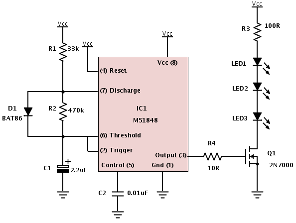
Building a device from a schematic
A common issue encountered is that individuals possess a schematic, also known as a circuit diagram, that they wish to construct. However, they discover that there are...
Building a circuit from a schematic requires a clear understanding of the components involved...
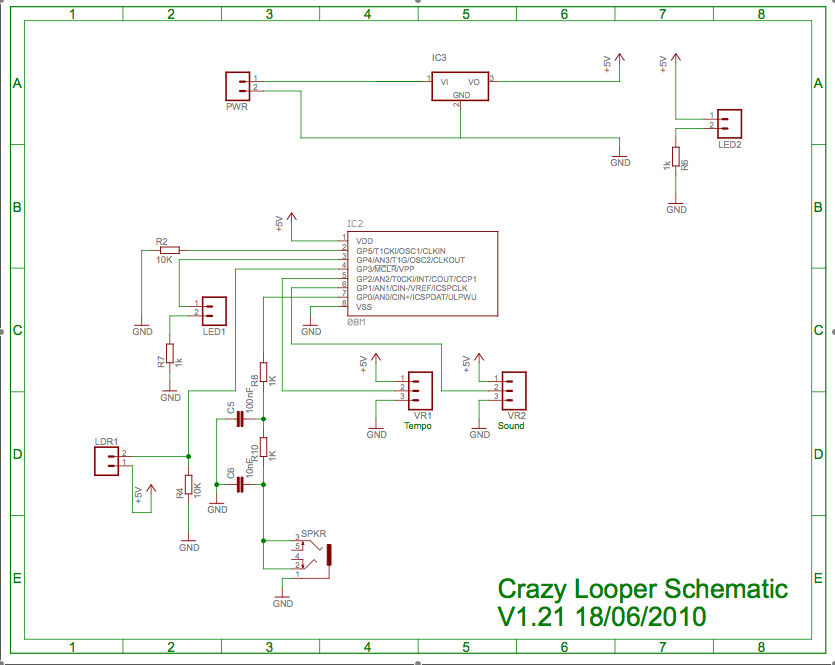
Crazy Looper Schematic
Two schematics are provided, one depicting the circuit without a programming port and the other including a programming port.
The first schematic represents a basic electronic circuit configuration that operates independently of a programming interface. This design may be suitable for...
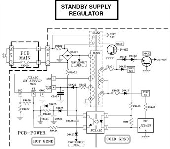
Need to have the circuit schematic for LG 29SA1RL model
The schematic is in PDF format and cannot be sent through this site. It is recommended to check a specific website that contains various schematics, including older posts that might have the schematic needed. A WS-55807 model is experiencing issues...
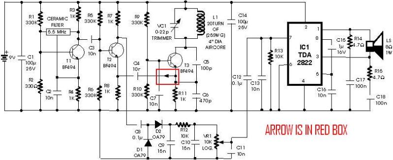
metal detector project circuit
A schematic diagram for a metal detector has been found. The project does not need to be original and can be sourced from the internet. There are several questions regarding this schematic. One query pertains to a small arrow connected...
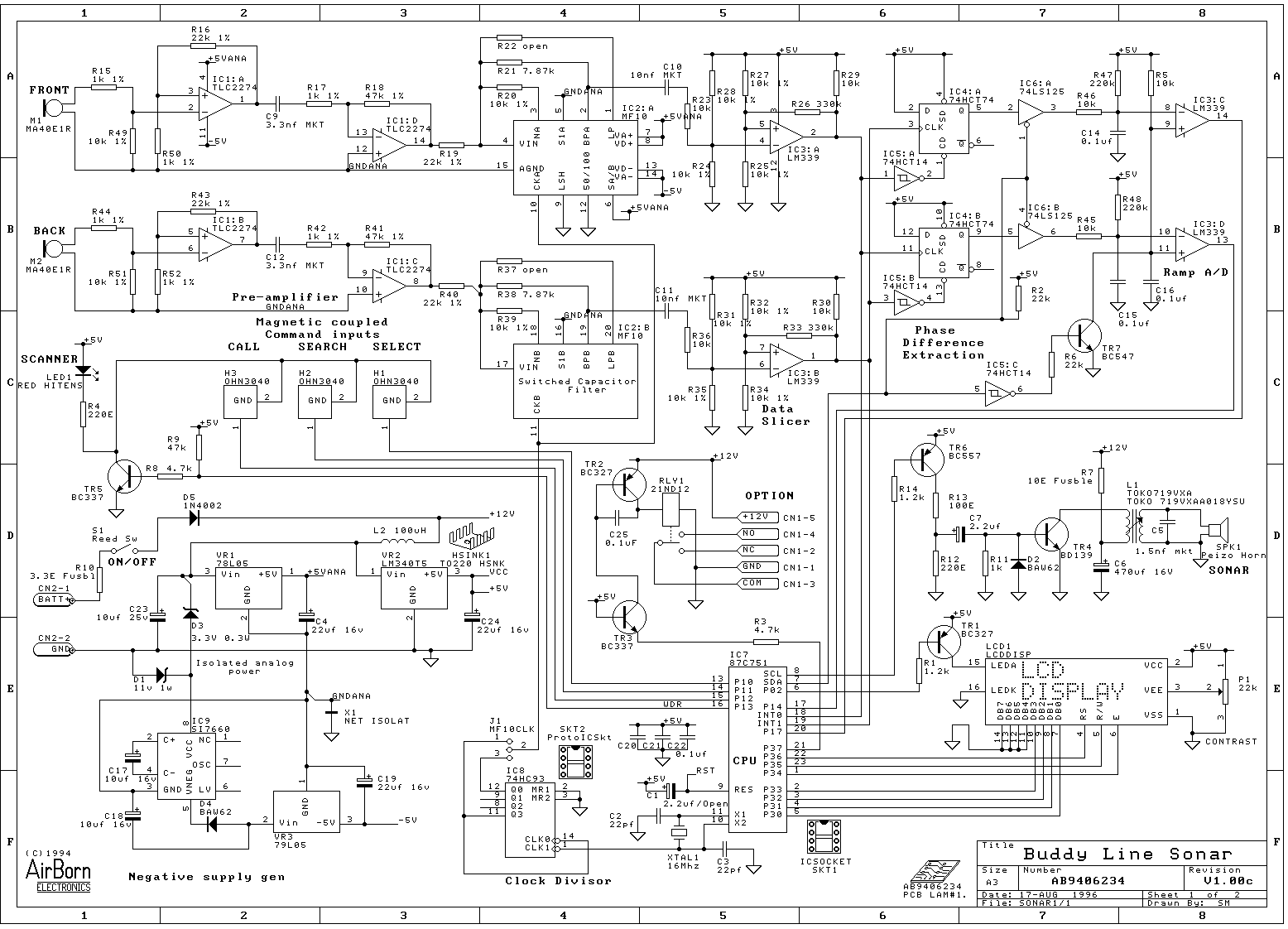
AirBorn Electronics project
Embedded system design engineers create examples of their work from the 1990s era.
Embedded systems have evolved significantly since the 1990s, and the design work from that period reflects the technological limitations and innovations of the time. Engineers in this field...
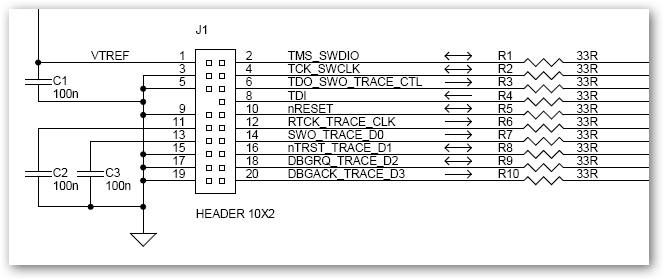
ULINKpro Interface Schematic
This interface schematic illustrates the JTAG, Serial Wire, and ETM interface circuits of ULINKpro. It can be utilized to analyze potential issues with the target hardware.
The schematic represents the interconnections and functionalities of the JTAG (Joint Test Action Group),...
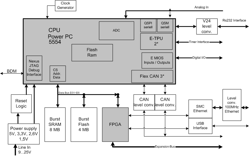
Electronics Engineering Herald - online magazine of electronics -home
Embedded systems serve as the core of most electronics-based systems, enabling data access, processing, storage, and control. While some simple electronic circuits can be designed without a microprocessor or microcontroller, this approach is often economically impractical, except for basic passive...
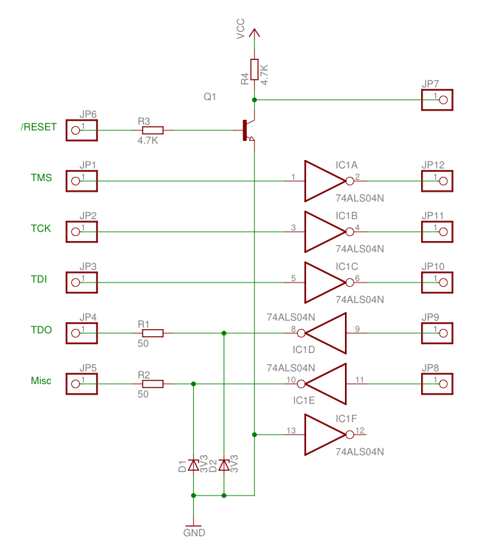
JTAG from a router
This is a quick hack on a veroboard instead of a neat PCB, but here is the schematic. Three outputs (TMS, TCK, TDI) are routed to the 74HC04 for buffering. The /RESET output directly drives a pull-down NPN transistor. The...
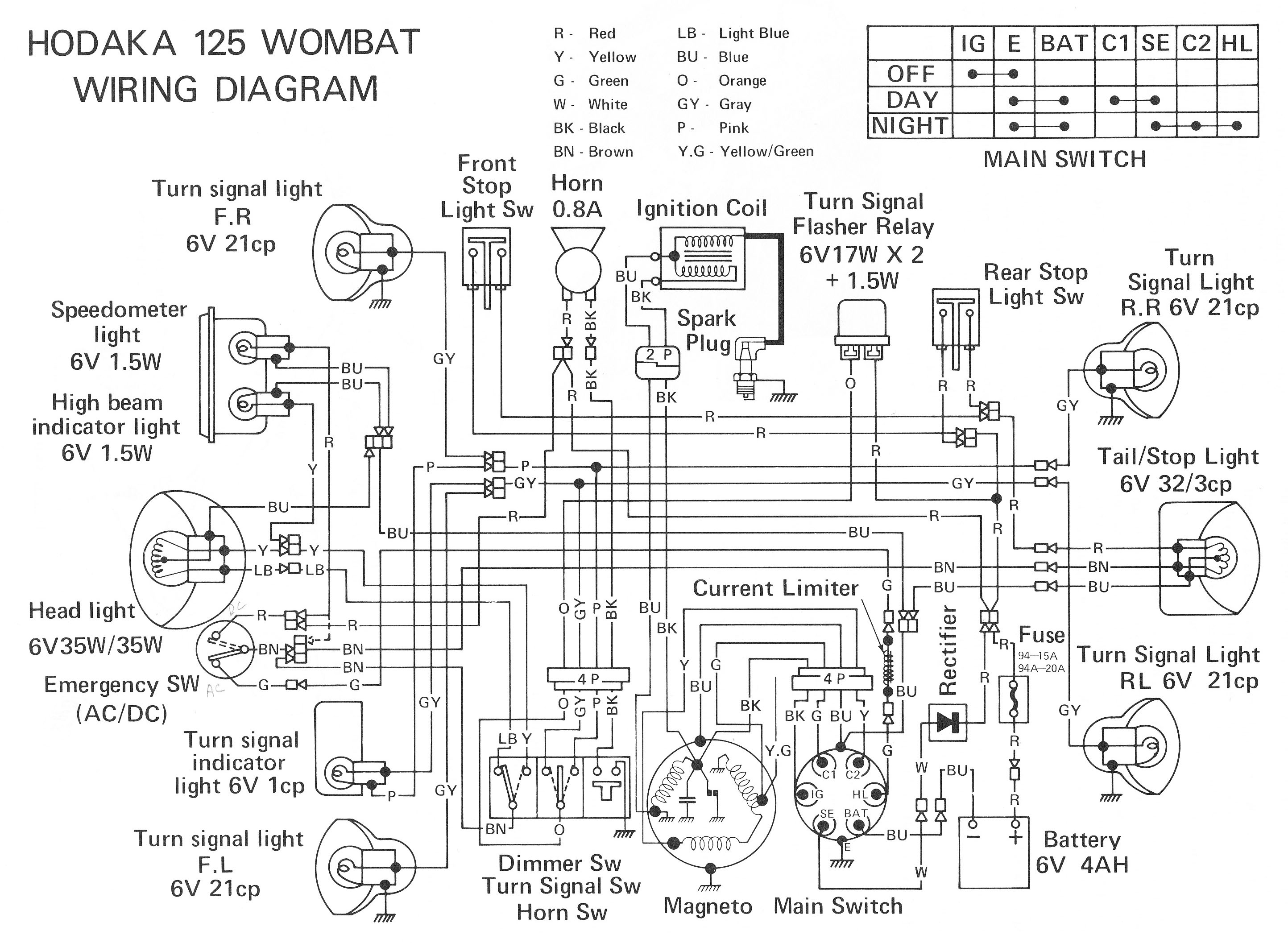
ELECTRONIC SCHEMATIC CIRCUIT DIAGRAMS
Electronic Schematic Circuit Diagrams Manual PDF Download.
The document provides a comprehensive manual that focuses on electronic schematic circuit diagrams. These diagrams are essential tools for understanding and designing electronic circuits, offering visual representations of circuit components and their interconnections. The...