


PS2 mouse and BASIC Stamp computer
#PS2 mouse
#BASIC Stamp
#computer interface
#input device
#X-axis
#Y-axis
#mouse motion
#serial communication
#embedded systems
Description: A mouse operates on two axes: "X" and "Y". When the mouse is moved horizontally, the "X" wheel inside the mouse rotates, and when moved vertically, the "Y" wheel rotates. The movement of the mouse results in the wheels moving according to the horizontal and vertical components of the motion. The wheels contain holes that, when rotated, interrupt the infra-red (IR) light emitted by an IR Light Emitting Diode (LED) at a rate proportional to the wheel's rotation. This interruption allows the mouse to count the number of increments (or ticks) the axis has moved over time. To determine the direction of movement, two light sensors, located close together along an axis parallel to the wheel's movement, are utilized. These sensors, referred to as "A" and "B", are part of a single 3-pin component. Initially, when the wheel is in a position that blocks IR light from reaching both sensors, the light will eventually reach one sensor, such as sensor "A", as the wheel rotates. Continuing in the same direction, the light will then reach sensor "B", followed by blocking sensor "A" and finally sensor "B" again.
The communication between the mouse circuitry and the personal computer (PC) is facilitated through PS/2 signals. The circuit board includes a microcontroller, the "SPCP05A", manufactured by Sunplus Technology Co., which is a versatile microcontroller with an instruction set, RAM, ROM, and internal timers. The chip interfaces with three pairs of light sensors (X, Y, Z) for horizontal, vertical, and middle mouse wheel movements. The IR LEDs are connected to the microcontroller's pin instead of directly to ground, which is a significant design feature. Initial experiments involved simulating the wheel's rotation by moving an object through the IR beam, successfully causing cursor movement. Further experiments involved replacing the sensor with wires to simulate sensor activity, allowing for cursor control through manual connections.
To automate this process, relays controlled by RS-232 were implemented, enabling the connection of sensor signals to the power terminal without manual intervention. During testing, it was discovered that the IR light might be pulsing at a high frequency, which the microcontroller expects to receive. This pulsing allows the system to differentiate between ambient light and the intended IR signal, ensuring proper functionality. The IR LEDs are pulsed at a frequency of approximately 38 kHz, while information is conveyed through lower frequency interruptions of the light. This modulation technique effectively filters out interference from constant IR sources, ensuring reliable operation of the mouse.
The design of the PS/2 mouse circuit board highlights the importance of the microcontroller's role in controlling the IR LEDs and interpreting the sensor inputs. The ability to pulse the IR LEDs allows the system to reject stray signals and maintain accurate tracking of the mouse's movements. Special IR sensors that are tuned to specific modulated frequencies can further enhance performance, ensuring that the mouse operates effectively in various lighting conditions. This sophisticated interplay of components and signals illustrates the complexity and functionality of modern mouse technology.A mouse has two axes: "X" and "Y". When the mouse is moved "horizontally", the "X" wheel inside the mouse rotates. When the mouse is moved "vertically" (upon a surface), the "Y" wheel inside the mouse rotates. For arbitrary mouse motion, the "X" and "Y" wheels move according to the "horizontal" and "vertical" components of the mouse motion. Notice the holes in the wheels inside the mouse. When the wheel rotates, the infra-red (IR) light emitted by an IR Light Emitting Diode (LED) is interrupted repeatedly, at a rate proportional to the rate of wheel rotation. Thus, the mouse knows how many "increments" (also called "ticks") the mouse axis has moved in a particular time period.
Determining the direction of movement involves the use of 2 light sensors, located very close together, along an axis parallel to the movement of the wheel. (Both sensors are in a single 3-pin component shown below. ) Let us name the two sensors in the package "A" and "B". Suppose the wheel is initially at a rotation angle such that the IR light is blocked from reaching both sensors.
As the wheel rotates, the IR light from the emitter will eventually be able to pass through a hole in the wheel and reach one of the two sensors, such as sensor "A". If the wheel continues rotating in the same direction, eventually the second sensor, "B", will be able to received IR light.
If the wheel continues rotating in the same direction, eventually the IR light will be blocked from reaching sensor "A". If the wheel continues rotating in the same direction, eventually the IR light will be blocked from reaching sensor "B".
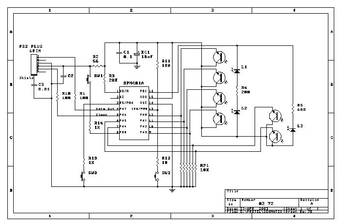
To understand more about how the mouse circuitry interprets the light sensors and communicates with the personal computer (PC) (via PS/2 signals), I studied the circuit board. A search of the Internet for the word "SPCP05A" indicates that the chip is manufactured by a company named "Sunplus Technology Co.
". Information about the "SPCP05A" microchip can be acquired from that company. The "SPCP05A" is actually a tiny computer! It has an instruction set, and RAM, and ROM, and internal timers, etc. In fact, the description of the "SPCP05A" microchip in the information provided by Sunplus Co. scarcely refers to the specific use of the microchip for "computer mouse" circuits. This chip is a versatile microcontroller. The three pairs of light sensors, ({ "X", "Y", "Z" }, for { horizontal movement, vertical movement, and middle mouse wheel }) send signals directly to other inputs on the chip. One thing I didn`t initially understand was the way the IR LEDs were connected to the microchip (pin 16 : "PB1"), instead of their negative terminals (cathode) simply being connected directly to ground.
This is important! The first thing I tried was moving an object between the IR LED and the sensor pair - to simulate the effect of the rotating wheel within the mouse. This worked. I could cause the mouse cursor to move around the screen by simply moving an obstacle through the IR light beam repeatedly, in the same direction.
Next, I removed the 3-pin sensor part from the mouse circuit board, and attached wires to circuit board in place of the sensor. I manually connected a wire to the positive voltage to simulate sensor activity. I connected the two signals to the power according to the following pattern (such that "0" represents "off", and "1" represents "on"): This worked.
I could move the mouse cursor on the screen by this tedious connecting and disconnecting of wires in the pattern shown above. Reversing the pattern from the current status in the sequence would move the cursor in the opposite direction.
Because things were going so well, I decided to connect the wires to relays (controlled by RS-232). This would essentially allow me to do exactly what I did with loose wires: connect the sensor signals to the power terminal in the appropriate sequence. The only difference would be the fact that the human (me) wouldn`t have to do the tedious connecting and disconnecting.
After a lot of adjusting of resistors and capacitors, etc, I made a strange discovery: If I was touching certain terminals in the circuit, it worked perfectly! The solution to this mystery appears in the next section. After some frustrating experiments I had a new thought: The IR light might be pulsing at a high frequency, and the chip might expect to receive this frequency.
Constant light (or my simulated constant sensor output) might be rejected. I was somewhat perplexed by the fact that the ambient light of a halogen floor lamp was acceptable, but I knew that even incandescent lamps have detectable modulation. That was it! The IR LEDs in the mouse circuit board must be flashing at high speed, and the microchip must expect this flashing in addition to the relatively low rate of light interruption by the rotating wheel (with holes).
By pulsing the IR LEDs, and expecting this pulsing in an unblocked sensor output signal, the chip can reject any ambient IR signals from interfering with mouse operation. For example, stray light from other (constant) IR sources won`t interefere with the mouse. I connected an audio amplifier to the sensor output, and then I let the sensor take in the ambient light cast by my halogen floor lamp.
I heard a distinct tone (60 Hz). When I dimmed the lamp, the tone grew faint, and finally stopped when the light was off. So, this sensor easily picks up the 60 Hz modulation in the incandescent bulb of my halogen floor lamp! Looking, now, at the schematic of the PS/2 mouse circuit board, the significance of the IR LEDs being connected to a pin on the microchip (instead of to the direct current) is obvious.
The microchip controls the flashing of the IR LEDs through the I/O pin, and the microchip can correlate its intention to flash the ID LEDs with the received sensor inputs, and thus reject any stray signals (due to non-flashing IR light). (However, correlation isn`t necessary. Simply detecting a minimum number of flashing counts could be a threshold for accepting sensor input.
) You can find special IR sensors, packaged in transistor-like form with three leads, that are "tuned" to specific modulated IR light frequencies (e. g. , 38 kHz). So, the IR LED can generally be pulsed at a frequency of 38 kHz so that the sensor will receive the light and let the electrical signal go to the sensor outputs.
To convey information, the light from the IR LED can be interrupted at a relatively low rate (e. g. , 1 to 100 times per second). This low-frequency pulsing is in conjunction with the steady high-frequency pulsing; i. e. , the low-frequency pulsing can be regarded as modulating the high-frequency pulsing. The high-frequency pulsing is like a "carrier wave" upon which the information signal (the relatively low-frequency modulation) is carried. However, I verified that the IR sensors in the Microsoft Intelhompt to
The communication between the mouse circuitry and the personal computer (PC) is facilitated through PS/2 signals. The circuit board includes a microcontroller, the "SPCP05A", manufactured by Sunplus Technology Co., which is a versatile microcontroller with an instruction set, RAM, ROM, and internal timers. The chip interfaces with three pairs of light sensors (X, Y, Z) for horizontal, vertical, and middle mouse wheel movements. The IR LEDs are connected to the microcontroller's pin instead of directly to ground, which is a significant design feature. Initial experiments involved simulating the wheel's rotation by moving an object through the IR beam, successfully causing cursor movement. Further experiments involved replacing the sensor with wires to simulate sensor activity, allowing for cursor control through manual connections.
To automate this process, relays controlled by RS-232 were implemented, enabling the connection of sensor signals to the power terminal without manual intervention. During testing, it was discovered that the IR light might be pulsing at a high frequency, which the microcontroller expects to receive. This pulsing allows the system to differentiate between ambient light and the intended IR signal, ensuring proper functionality. The IR LEDs are pulsed at a frequency of approximately 38 kHz, while information is conveyed through lower frequency interruptions of the light. This modulation technique effectively filters out interference from constant IR sources, ensuring reliable operation of the mouse.
The design of the PS/2 mouse circuit board highlights the importance of the microcontroller's role in controlling the IR LEDs and interpreting the sensor inputs. The ability to pulse the IR LEDs allows the system to reject stray signals and maintain accurate tracking of the mouse's movements. Special IR sensors that are tuned to specific modulated frequencies can further enhance performance, ensuring that the mouse operates effectively in various lighting conditions. This sophisticated interplay of components and signals illustrates the complexity and functionality of modern mouse technology.A mouse has two axes: "X" and "Y". When the mouse is moved "horizontally", the "X" wheel inside the mouse rotates. When the mouse is moved "vertically" (upon a surface), the "Y" wheel inside the mouse rotates. For arbitrary mouse motion, the "X" and "Y" wheels move according to the "horizontal" and "vertical" components of the mouse motion. Notice the holes in the wheels inside the mouse. When the wheel rotates, the infra-red (IR) light emitted by an IR Light Emitting Diode (LED) is interrupted repeatedly, at a rate proportional to the rate of wheel rotation. Thus, the mouse knows how many "increments" (also called "ticks") the mouse axis has moved in a particular time period.
Determining the direction of movement involves the use of 2 light sensors, located very close together, along an axis parallel to the movement of the wheel. (Both sensors are in a single 3-pin component shown below. ) Let us name the two sensors in the package "A" and "B". Suppose the wheel is initially at a rotation angle such that the IR light is blocked from reaching both sensors.
As the wheel rotates, the IR light from the emitter will eventually be able to pass through a hole in the wheel and reach one of the two sensors, such as sensor "A". If the wheel continues rotating in the same direction, eventually the second sensor, "B", will be able to received IR light.
If the wheel continues rotating in the same direction, eventually the IR light will be blocked from reaching sensor "A". If the wheel continues rotating in the same direction, eventually the IR light will be blocked from reaching sensor "B".
To understand more about how the mouse circuitry interprets the light sensors and communicates with the personal computer (PC) (via PS/2 signals), I studied the circuit board. A search of the Internet for the word "SPCP05A" indicates that the chip is manufactured by a company named "Sunplus Technology Co.
". Information about the "SPCP05A" microchip can be acquired from that company. The "SPCP05A" is actually a tiny computer! It has an instruction set, and RAM, and ROM, and internal timers, etc. In fact, the description of the "SPCP05A" microchip in the information provided by Sunplus Co. scarcely refers to the specific use of the microchip for "computer mouse" circuits. This chip is a versatile microcontroller. The three pairs of light sensors, ({ "X", "Y", "Z" }, for { horizontal movement, vertical movement, and middle mouse wheel }) send signals directly to other inputs on the chip. One thing I didn`t initially understand was the way the IR LEDs were connected to the microchip (pin 16 : "PB1"), instead of their negative terminals (cathode) simply being connected directly to ground.
This is important! The first thing I tried was moving an object between the IR LED and the sensor pair - to simulate the effect of the rotating wheel within the mouse. This worked. I could cause the mouse cursor to move around the screen by simply moving an obstacle through the IR light beam repeatedly, in the same direction.
Next, I removed the 3-pin sensor part from the mouse circuit board, and attached wires to circuit board in place of the sensor. I manually connected a wire to the positive voltage to simulate sensor activity. I connected the two signals to the power according to the following pattern (such that "0" represents "off", and "1" represents "on"): This worked.
I could move the mouse cursor on the screen by this tedious connecting and disconnecting of wires in the pattern shown above. Reversing the pattern from the current status in the sequence would move the cursor in the opposite direction.
Because things were going so well, I decided to connect the wires to relays (controlled by RS-232). This would essentially allow me to do exactly what I did with loose wires: connect the sensor signals to the power terminal in the appropriate sequence. The only difference would be the fact that the human (me) wouldn`t have to do the tedious connecting and disconnecting.
After a lot of adjusting of resistors and capacitors, etc, I made a strange discovery: If I was touching certain terminals in the circuit, it worked perfectly! The solution to this mystery appears in the next section. After some frustrating experiments I had a new thought: The IR light might be pulsing at a high frequency, and the chip might expect to receive this frequency.
Constant light (or my simulated constant sensor output) might be rejected. I was somewhat perplexed by the fact that the ambient light of a halogen floor lamp was acceptable, but I knew that even incandescent lamps have detectable modulation. That was it! The IR LEDs in the mouse circuit board must be flashing at high speed, and the microchip must expect this flashing in addition to the relatively low rate of light interruption by the rotating wheel (with holes).
By pulsing the IR LEDs, and expecting this pulsing in an unblocked sensor output signal, the chip can reject any ambient IR signals from interfering with mouse operation. For example, stray light from other (constant) IR sources won`t interefere with the mouse. I connected an audio amplifier to the sensor output, and then I let the sensor take in the ambient light cast by my halogen floor lamp.
I heard a distinct tone (60 Hz). When I dimmed the lamp, the tone grew faint, and finally stopped when the light was off. So, this sensor easily picks up the 60 Hz modulation in the incandescent bulb of my halogen floor lamp! Looking, now, at the schematic of the PS/2 mouse circuit board, the significance of the IR LEDs being connected to a pin on the microchip (instead of to the direct current) is obvious.
The microchip controls the flashing of the IR LEDs through the I/O pin, and the microchip can correlate its intention to flash the ID LEDs with the received sensor inputs, and thus reject any stray signals (due to non-flashing IR light). (However, correlation isn`t necessary. Simply detecting a minimum number of flashing counts could be a threshold for accepting sensor input.
) You can find special IR sensors, packaged in transistor-like form with three leads, that are "tuned" to specific modulated IR light frequencies (e. g. , 38 kHz). So, the IR LED can generally be pulsed at a frequency of 38 kHz so that the sensor will receive the light and let the electrical signal go to the sensor outputs.
To convey information, the light from the IR LED can be interrupted at a relatively low rate (e. g. , 1 to 100 times per second). This low-frequency pulsing is in conjunction with the steady high-frequency pulsing; i. e. , the low-frequency pulsing can be regarded as modulating the high-frequency pulsing. The high-frequency pulsing is like a "carrier wave" upon which the information signal (the relatively low-frequency modulation) is carried. However, I verified that the IR sensors in the Microsoft Intelhompt to

Basic Stamp Based Altimeter
A method for determining altitude involves the use of barometric pressure; however, it presents certain challenges. The relationship between pressure and altitude is not linear but rather complex, a concept developed by the army in the 1930s. The equation for...
Microcontroller circuits
Connect the serial cable to the serial port. If using a USB to TTL, RS232, or serial converter, plug it into the USB port. Next, short the Tx pin to the Rx pin or the TxD pin to the RxD...
Beginning Embedded Electronics - 2
Acquire all the components required for this lecture here. It is highly recommended to obtain a multimeter with a continuity setting. A quality multimeter with this feature typically costs around $60, while premium models can reach $300. The $60 option...
AirBorn Electronics project
Embedded system design engineers create examples of their work from the 1990s era.
Embedded systems have evolved significantly since the 1990s, and the design work from that period reflects the technological limitations and innovations of the time. Engineers in this field...
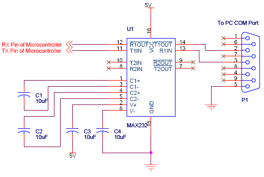
serial communication introduction
Serial communication using UART or USART of a microcontroller 8051 AVR PIC, software implementation of half-duplex UART and MAX232 interfacing with microcontrollers 8051 AVR PIC.
The described system focuses on implementing serial communication via UART (Universal Asynchronous Receiver-Transmitter) or USART (Universal...
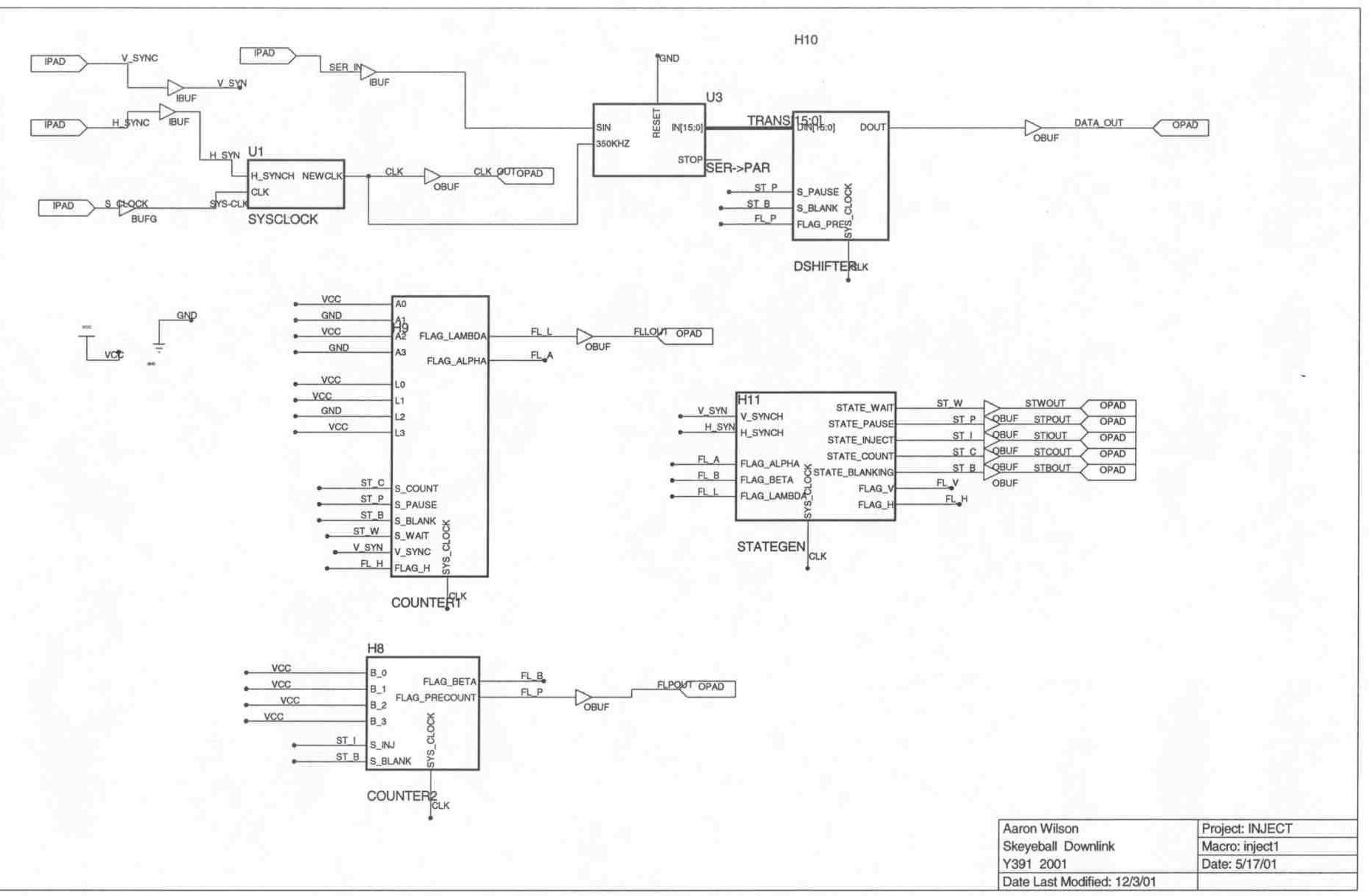
Downlink Project Description
The Skeyeball project is an ongoing initiative within the Indiana University System Design Methods Laboratory, aimed at providing graduate and undergraduate students with opportunities to engage in embedded system design and implement various projects. The downlink segment of the project...
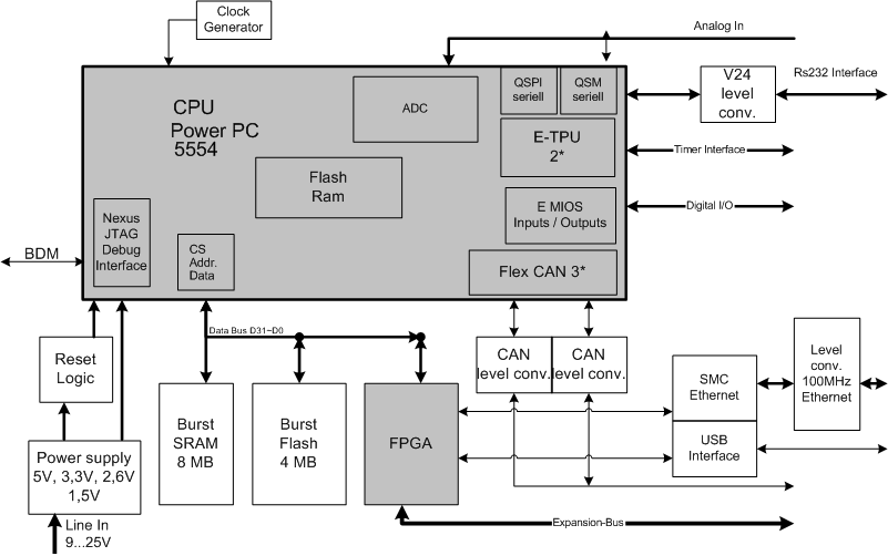
Electronics Engineering Herald - online magazine of electronics -home
Embedded systems serve as the core of most electronics-based systems, enabling data access, processing, storage, and control. While some simple electronic circuits can be designed without a microprocessor or microcontroller, this approach is often economically impractical, except for basic passive...