


Reset Protection For Computers
#reset protection
#computer
#motherboard
#protection circuit
#switch
#earth connection
#electronics
#safety
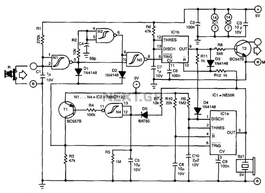
Description: This protection circuit is placed between the reset switch and the motherboard. The earth connection of the computer must be linked to the terminal of the protection circuit. The protection circuit can draw its power from the computer supply. When the circuit is installed, activating the reset switch will not immediately restart the computer. Instead, a buzzer will sound to alert the user of the reset operation. The buzzer is activated for 4 seconds by monostable IC1A, which is triggered by the reset switch. During these 4 seconds, the output pin 5 of IC1A ensures that the reset function (pin 10) of IC1B is disabled. When the reset switch is pressed again, monostable IC1B will be triggered, initiating the reset procedure. Transistor T2 is then activated for 0.5 seconds, and the buzzer is deactivated via resistor R11 and diode D4. The circuit configuration around T1 and N4 ensures that IC1A can accept trigger pulses again 10 seconds after the monostable time of IC1B has elapsed. This design prevents unauthorized operation of the reset switch, such as by children.
This protection circuit serves as a safeguard for the motherboard’s reset functionality, effectively preventing accidental resets that could disrupt system operation. The circuit is powered by the computer's supply, ensuring it remains functional without requiring additional power sources.
The operation begins when the reset switch is pressed. IC1A, a monostable multivibrator, generates a pulse that triggers the buzzer for a duration of 4 seconds. During this time, output pin 5 of IC1A disables the reset function of IC1B, preventing an immediate restart of the computer. This delay is crucial as it not only alerts the user with an audible signal but also prevents unintended resets.
Upon a second press of the reset switch, IC1B is triggered, initiating the reset process. The activation of transistor T2 for 0.5 seconds allows the buzzer to turn off, indicating the end of the alert period. The use of resistor R11 and diode D4 in this stage ensures that the buzzer is efficiently deactivated without affecting the overall circuit functionality.
Furthermore, the design includes a delay mechanism that allows IC1A to accept new trigger pulses only after 10 seconds following the completion of IC1B's monostable time. This feature is particularly beneficial in environments where accidental resets by children or unauthorized personnel may occur, providing an additional layer of protection for the system.
In summary, this protection circuit enhances the reliability and usability of the reset function in a computer system, combining alert mechanisms with safeguards to prevent unintended operations. Its thoughtful design ensures that the user is adequately informed while maintaining control over the reset process. This protection circuit is inserted between the reset switch and the motherboard. The earth connection of th e computer must be linked to terminal of the protection circuit. The protection circuit can draw its power from the computer supply. When the circuit has been fitted, operation of the reset switch will not immediately restart the computer. Instead, a buzzer will sound to alert you to the reset operation. The buzzer is actuated for 4 s by monostable IC1A, which is triggered by the reset switch. During these 4 s, the output, pin 5, of IC1A ensures that the reset function, pin 10, of IC1B is disabled.
When the reset switch is operated again, monostable IC IB will be triggered and this starts the reset procedure. Transistor T2 is then switched on for 0.5 s and the buzzer is deactuated via Rll and D4. The circuit around T1 and N4 ensures that IC1A can accept trigger pulses again 10 s after the mono time of IC1B has lapsed.
This arrangement prevents, for example, children operating the reset switch.
This protection circuit serves as a safeguard for the motherboard’s reset functionality, effectively preventing accidental resets that could disrupt system operation. The circuit is powered by the computer's supply, ensuring it remains functional without requiring additional power sources.
The operation begins when the reset switch is pressed. IC1A, a monostable multivibrator, generates a pulse that triggers the buzzer for a duration of 4 seconds. During this time, output pin 5 of IC1A disables the reset function of IC1B, preventing an immediate restart of the computer. This delay is crucial as it not only alerts the user with an audible signal but also prevents unintended resets.
Upon a second press of the reset switch, IC1B is triggered, initiating the reset process. The activation of transistor T2 for 0.5 seconds allows the buzzer to turn off, indicating the end of the alert period. The use of resistor R11 and diode D4 in this stage ensures that the buzzer is efficiently deactivated without affecting the overall circuit functionality.
Furthermore, the design includes a delay mechanism that allows IC1A to accept new trigger pulses only after 10 seconds following the completion of IC1B's monostable time. This feature is particularly beneficial in environments where accidental resets by children or unauthorized personnel may occur, providing an additional layer of protection for the system.
In summary, this protection circuit enhances the reliability and usability of the reset function in a computer system, combining alert mechanisms with safeguards to prevent unintended operations. Its thoughtful design ensures that the user is adequately informed while maintaining control over the reset process. This protection circuit is inserted between the reset switch and the motherboard. The earth connection of th e computer must be linked to terminal of the protection circuit. The protection circuit can draw its power from the computer supply. When the circuit has been fitted, operation of the reset switch will not immediately restart the computer. Instead, a buzzer will sound to alert you to the reset operation. The buzzer is actuated for 4 s by monostable IC1A, which is triggered by the reset switch. During these 4 s, the output, pin 5, of IC1A ensures that the reset function, pin 10, of IC1B is disabled.
When the reset switch is operated again, monostable IC IB will be triggered and this starts the reset procedure. Transistor T2 is then switched on for 0.5 s and the buzzer is deactuated via Rll and D4. The circuit around T1 and N4 ensures that IC1A can accept trigger pulses again 10 s after the mono time of IC1B has lapsed.
This arrangement prevents, for example, children operating the reset switch.

Safety / Protection Circuits
To prevent deep discharge that can damage or shorten the life of a rechargeable battery, it is essential to disconnect its load before the battery is completely discharged. The circuit protects against AC line disturbances by switching off the power...
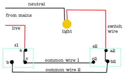
2 Way Switch Wire Electrical
The following circuit illustrates a 2-way switch wiring electrical circuit diagram. Features include the ability to turn on the lights using switch S1, which has three terminals.
The 2-way switch circuit is commonly used in residential and commercial applications to control...
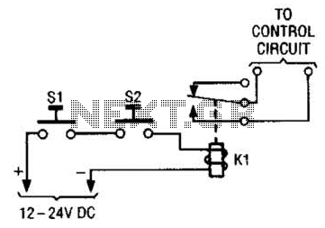
Simple Safety Circuit Circuit
The simple two-hand safety control switch consists of two pushbutton switches connected in series; both must be depressed to energize the relay.
The two-hand safety control switch is designed to enhance safety in applications where the operation of machinery or equipment...
How To Build A Simple Code-Operated Switch
This is a simplified version of the Universal Keypad-Operated Switch. The design has been modified to reduce circuit complexity and the number of components required, resulting in somewhat less secure code functionality. However, it remains adequate for many applications. The...
Protection Circuit For Electrical Appliances From Power Supply Variations PCB
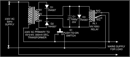
This is a low-cost protection circuit designed to safeguard electrically operated home appliances, such as TVs, DVD players, refrigerators, and other devices, during sudden power outages and the subsequent restoration of mains supply. Appliances like refrigerators and air conditioners are...
Intelligent trailing switch
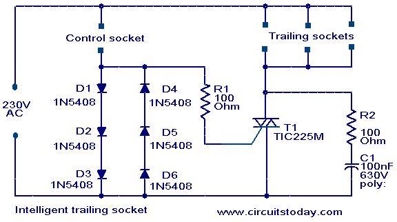
This circuit is a straightforward yet effective design where devices connected to the trailing sockets will operate only when the device connected to the control socket is powered on. For instance, if a motor is connected to the control socket...
Structure and working principles of various protective circuit diagram e
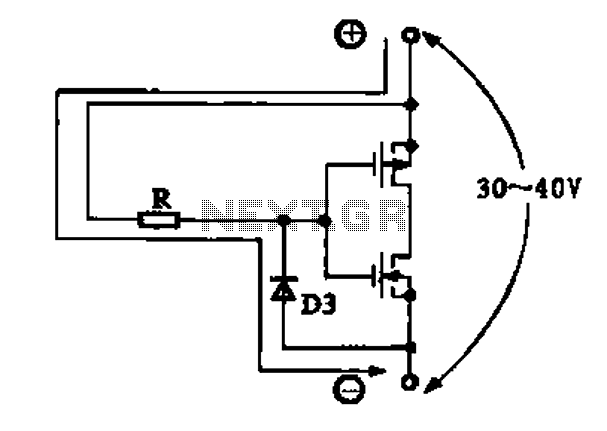
Due to the varying conditions of different input signals, when an abnormal voltage is applied to the pin, protection circuits are established to create a circuit path from the LSI (large scale integration) circuits for internal protection. The structure and...
Do not drink and drive I wish you a safe journey home Language Integrated Circuits
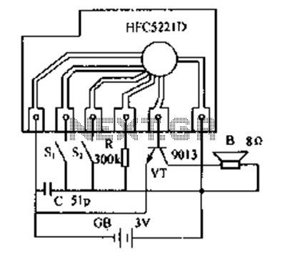
Do not drink and drive. Wishing you a safe journey home. Language Integrated Circuits.
Language Integrated Circuits (LICs) are specialized electronic components designed to facilitate the processing of language-based data within various applications. These circuits integrate multiple functions, such as signal...
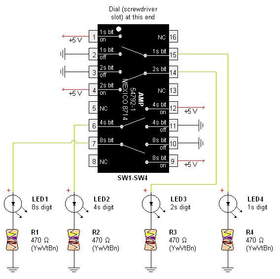
AMP Hexadecimal Rotary Switch
Pictures and a sample schematic (including pinouts) of an AMP hexadecimal (16-position) switch with a screw slot actuator.
The AMP hexadecimal switch is a 16-position rotary switch designed for applications requiring multiple selectable options. This switch features a screw slot actuator...