


TDS9092 TDS971 IEEE-488/RS232C
#IEEE-488
#RS232
#communication board
#Eurocard
#baud rate
#DIP switch
#ribbon cable
#TDS2020F
#TDS9092
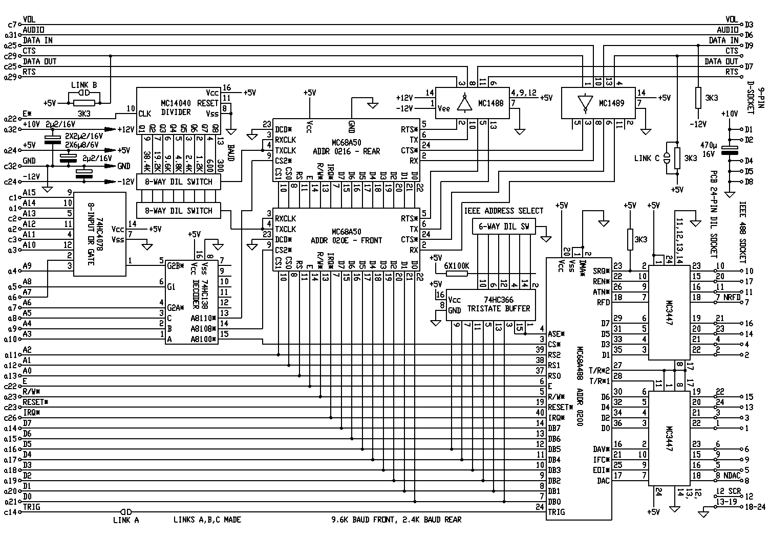
Description: This is a Eurocard communications board designed for TDS2020F or TDS9092 computers, as well as earlier models. It features an IEEE-488 Talker/Listener interface and two RS232 ports supporting baud rates from 75 to 38400. A DIP switch on the board allows selection of the IEEE address. The board is supplied with a 45 cm ribbon cable terminated in an IEEE-488 specification socket for convenient mounting on the instrument. The TDS971 addresses are already utilized on the TDS9092 for internal RAM. To change the address of the board from 01xx to 02xx, signals must be interchanged to pins A4 and A5 of the TDS971 (address lines A8 and A9). The board adheres to a single Eurocard format (160mm x 100mm) and is equipped with a DIN 41612 type C connector, which consists of two rows of 32 pins spaced 5.04mm apart. Its pin connections are compatible with both the TDS2020F and TDS9092. The board requires a TDS9092-PLUG type for operation. The IEEE-488 interface connects to a 24-pin DIL socket located on the solder side of the board, into which the provided ribbon cable assembly is connected. The opposite end of the ribbon features an IEEE-488 24-pin socket for mounting on the instrument's case. The DIL plug must be inserted such that the ribbon cable faces the rear of the board to ensure correct IEEE-488 connections at the other end. Additionally, a 9-pin D-type socket located on the front of the board carries one of the two RS232 ports and provides power from the computer, which can be routed to a remote location. Two uncommitted signal wires connect from this socket to the backplane. For comprehensive usage details of an ACIA, refer to the manufacturer's data sheet (e.g., Motorola MC68A50 or Hitachi HD68A50). The board includes two of these devices to implement RS232 ports at both the front and rear. During the initialization sequence of the application, resetting the serial chip is crucial. It is important to note that this device employs a software reset rather than a hardware reset and must be configured according to the desired protocol. The board features two DIL switches for setting the baud rates of the serial ports, with only one switch of each pair needing to be closed; the corresponding rates are indicated on the board. One switch is designated for the front port while the other is for the rear port, allowing baud rates from 300 to 38400, derived from the E* clock. These rates assume the 68A50 is set for a divide by 16. If the divide by 64 setting is used, positions 1 and 2 will enable additional baud rates of 75 and 150, respectively. This functionality is facilitated by a Motorola MC68A488 chip (or an equivalent). For complete programming information, consult the manufacturer's data and application notes. Common applications of the interface are illustrated in subsequent examples. In the initialization routine executed after powering up, it is necessary to invert the reading from the IEEE address switches to account for the inverting buffer connecting them to the data bus. The IEEE chip requires a software reset, which must be included in the initialization process. This assumes the IEEE bus controller is correctly programmed for the data anticipated from the Forth system. In practical scenarios, the Forth system may attempt to transmit when the controller is not in a READ state, potentially causing it to remain in OUTIEEE indefinitely. Conversely, the controller may be in the midst of sending a string when the Forth system wishes to transmit. To simplify the BASIC programming of the controller, an alternative definition of !IEEE can be utilized.This is a Eurocard communications board for TDS2020F or TDS9092 computers (or earlier types). It contains an IEEE-488 Talker/Listener interface and two RS232 ports with all baud rates from 75 to 38400. A DIP switch on the board selects the IEEE address. The board comes complete with 45cm ribbon cable terminated in an IEEE-488 specification socket for mounting on your instrument. The TDS971 addresses are already used on the TDS9092 for internal RAM. Interchange the signals to pins a4 and a5 of the TDS971 (address lines A8 and A9). This will change the address of the board from 01xx to 02xx, and examples in this section have been changed to reflect this. The board is single Eurocard format (160mm x 100mm) and has a DIN 41612 type C connector (two rows of 32 pins 5.
04mm apart). Its pin connections correspond with both the TDS2020F and TDS9092 and are given below. You will need the TDS9092-PLUG type to work with this board. The IEEE-488 interface is brought to a 24-pin DIL socket on the solder side of the board into which the ribbon cable assembly provided with the board is plugged. The other end of the ribbon is an IEEE-488 24-pin socket for mounting on the case of the instrument. Put in the DIL plug so that the ribbon cable faces to the rear of the board. The IEEE-488 connections will then be correct on the other end of the ribbon cable. A third connector is a 9-pin D-type socket on the front of the board. It carries one of the two RS232 ports and also power from the computer which can be led to a remote location.
Two uncommitted signal wires go from this socket to the backplane. Pin connections are: For full details of use of an ACIA see the manufacturer`s data sheet (e. g. Motorola MC68A50 or Hitachi HD68A50). The following is an example of its use. There are two of these devices on the board implementing RS232 ports at both the front and rear of the board. In the initialisation sequence of the application it is essential to reset the serial chip. Note from the data sheet and circuit diagram that this device has a software, not hardware, reset. Then it is set up according to the desired protocol. For example: On the board are two DIL switches to set the baud rates of the serial ports. Only one of each switch must be closed and the associated rates are printed on the board alongside. One switch is for the front port the other for the rear one. Baud rates from 300 to 38400 can be set. They derive from the E* clock. These rates assume that the 68A50 was set for divide by 16. If divide by 64 is set then positions 1 and 2 make extra baud rates of 75 and 150 available respectively.
This is implemented using a Motorola MC68A488 chip (or equivalent). See the manufacturer`s data and application notes for full programming information. Some of the usual uses of the interface are shown in the following examples. In the initialisation routine executed after power-up note that the reading from the IEEE address switches has to be inverted to compensate for the inverting buffer connecting them to the data bus. The IEEE chip has a software reset and this has to be included in initialisations. The above assumes that the IEEE bus controller is correctly programmed for the data expected from the Forth system.
In practice the Forth system may try to send when the controller is not at a READ statement. It may therefore hold in OUTIEEE indefinitely. Alternatively the controller may be in the middle of sending a string when the Forth system wants to transmit. To avoid complicating the BASIC programming of the controller the following alternative definition of !IEEE can be used.
04mm apart). Its pin connections correspond with both the TDS2020F and TDS9092 and are given below. You will need the TDS9092-PLUG type to work with this board. The IEEE-488 interface is brought to a 24-pin DIL socket on the solder side of the board into which the ribbon cable assembly provided with the board is plugged. The other end of the ribbon is an IEEE-488 24-pin socket for mounting on the case of the instrument. Put in the DIL plug so that the ribbon cable faces to the rear of the board. The IEEE-488 connections will then be correct on the other end of the ribbon cable. A third connector is a 9-pin D-type socket on the front of the board. It carries one of the two RS232 ports and also power from the computer which can be led to a remote location.
Two uncommitted signal wires go from this socket to the backplane. Pin connections are: For full details of use of an ACIA see the manufacturer`s data sheet (e. g. Motorola MC68A50 or Hitachi HD68A50). The following is an example of its use. There are two of these devices on the board implementing RS232 ports at both the front and rear of the board. In the initialisation sequence of the application it is essential to reset the serial chip. Note from the data sheet and circuit diagram that this device has a software, not hardware, reset. Then it is set up according to the desired protocol. For example: On the board are two DIL switches to set the baud rates of the serial ports. Only one of each switch must be closed and the associated rates are printed on the board alongside. One switch is for the front port the other for the rear one. Baud rates from 300 to 38400 can be set. They derive from the E* clock. These rates assume that the 68A50 was set for divide by 16. If divide by 64 is set then positions 1 and 2 make extra baud rates of 75 and 150 available respectively.
This is implemented using a Motorola MC68A488 chip (or equivalent). See the manufacturer`s data and application notes for full programming information. Some of the usual uses of the interface are shown in the following examples. In the initialisation routine executed after power-up note that the reading from the IEEE address switches has to be inverted to compensate for the inverting buffer connecting them to the data bus. The IEEE chip has a software reset and this has to be included in initialisations. The above assumes that the IEEE bus controller is correctly programmed for the data expected from the Forth system.
In practice the Forth system may try to send when the controller is not at a READ statement. It may therefore hold in OUTIEEE indefinitely. Alternatively the controller may be in the middle of sending a string when the Forth system wants to transmit. To avoid complicating the BASIC programming of the controller the following alternative definition of !IEEE can be used.
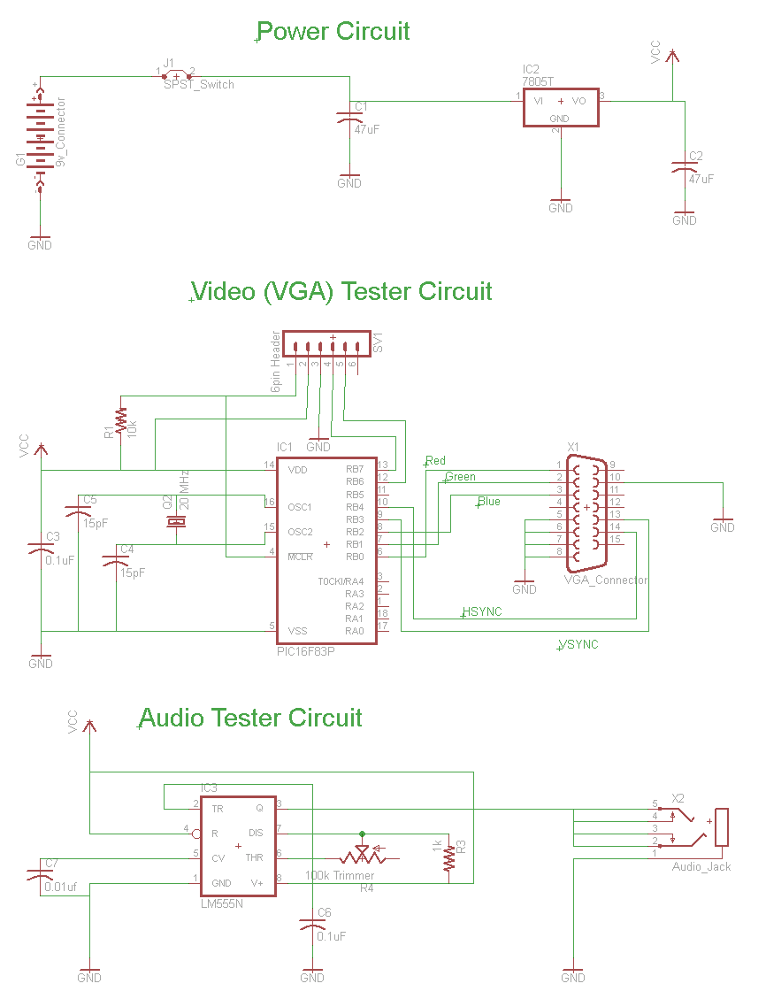
Simple RS232 Serial Interface Circuit
The circuit for the RS232 serial interface exhibits mild complexity. The primary components of the circuit include the 18F4520 microcontroller, MAX233A level shifter, and a DB-9 connector. This circuit utilizes a basic +5V power regulator to supply the digital signals...
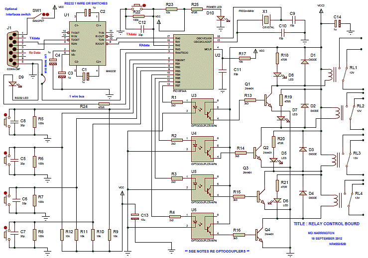
Rs 232 Relay Control Board
This device can be interfaced with various adapters, including a keypad adapter (optional), an RF receiver (optional), or via the internet (optional). It can also be adapted to operate with other external attachments.
The device features multiple interfacing options, enhancing its...
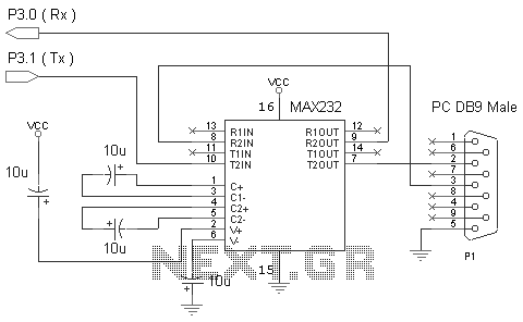
Communication using RS232 and MAX232 circuit
One of the most effective communication methods to be implemented in a digital system is the use of the RS232 serial line. The microcontroller 89S51 is equipped with a UART, allowing it to perform serial communication at RS232 levels with...
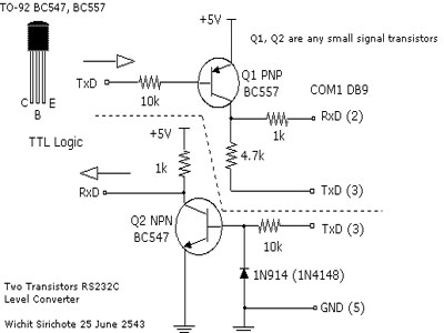
Simple RS 232 Level Converter
When connecting a microcontroller project to a COM port on a PC, an RS-232 converter is required. Various chips can accomplish this task, such as the MAX232 and DS275. However, for a simple and cost-effective RS-232 converter, the following circuit...
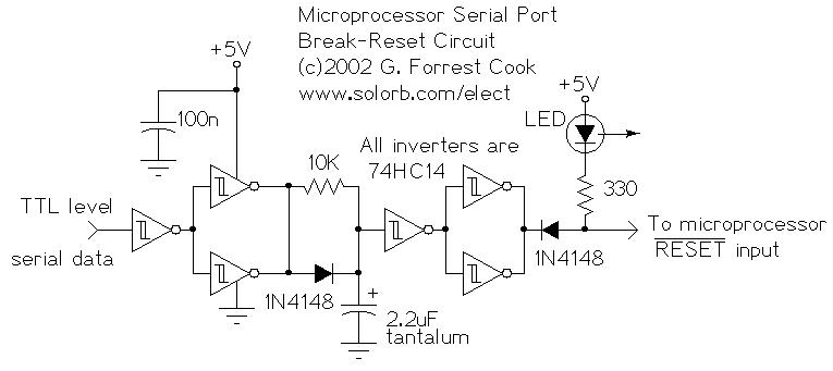
RS232 Reset for Microprocessor
This circuit enables a remote microprocessor to reset the control of a host by sending an interrupt signal over an RS-232 or RS-422 serial line. When the remote machine is restarted using a simple program loader, it may cause the...
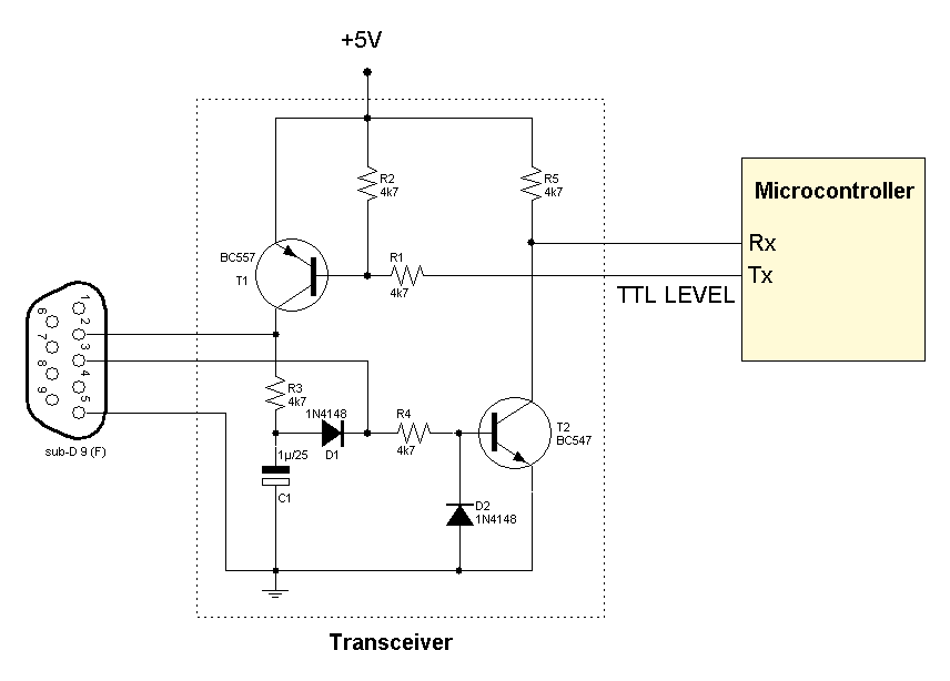
RS232 transceiver circuits
Several RS232 transceiver circuits are used for communication between microcontrollers and other devices, such as PCs or RS232 devices. This document presents a collection of well-known RS232 transceiver circuits. The circuit utilizes the MAX232 from Maxim's devices, which is recognized...
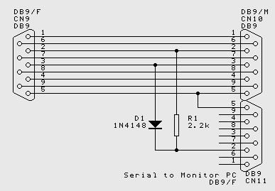
RS232 Connections wiring up
While the normal PC hardware might well run with just Tx, Rx and Ground connected, most driver software will wait forever for one of the handshaking lines to go to the correct level. Depending on the signal state it might...
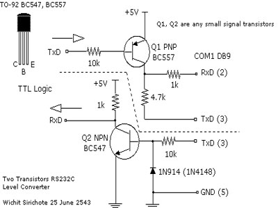
Simple RS 232 Level Converter
To connect a microcontroller project to the COM port of a PC, an RS-232 converter is required. Various chips are available to address this need, such as the MAX232 and DS275.
The RS-232 standard is widely used for serial communication between...
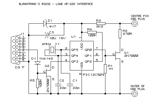
Blank Frank`s RS232 - Lowe HF-225 interface
If you have access to a Lowe HF-225 shortwave receiver, then you might be interested in this page. If you don't, then you'd probably be better off leaving now. What follows is a project I completed some time ago, which...