


There is an UART on the Nexus 4
#UART
#Nexus 4
#kernel
#Ubuntu Touch
#hackable
#Mer OBS
#serial communication
#embedded systems
#Linux
#mobile devices
Description: The Nexus 4 was chosen due to its traditionally open nature, exemplified by the availability of Ubuntu Touch images. Unexpectedly, it was discovered to be highly hackable. After packaging the Mako kernel on Mer OBS for a personal project, the package became available, although it did not boot properly. This experience rekindled memories of working on the Archos 5 IT with the openAOS project, leading to the idea of having a UART for debugging. A search on the internet yielded a lead from an XDA post, but it did not provide much assistance regarding the logic levels or which pins corresponded to the headphone socket. An initial check revealed no output from the port when attempting to pipe /dev/urandom to /dev/ttyHSL0. The circuit involved is a simple comparator with a reference voltage of 2.8V; if the input voltage exceeds this, the output switches to VCC (logic 1/true). This action triggers a switch that disables audio and activates a UART on R/RX and L/TX. A bench power supply was connected to the MIC and GND pins, set at 2.9V with a current limit of about 10mA, ensuring that GND was connected to + and MIC to -, resulting in -2.9V. The output was clean, although the RX port experienced some crosstalk. Unfortunately, incorrect cable connections during further experiments led to damaging the switch, rendering the UART unusable, though audio output remained functional. An update indicated that the MIC input should actually be +3V, which also appears to apply to other models. There is an invitation for others to try this on different Nexus devices. For those interested in building a cable, examples include a 3.5mm 4-pin and a 3.3V USB to Serial cable based on an FTDI chip.
The Nexus 4 device features a unique architecture that allows for extensive modifications and debugging capabilities. The UART (Universal Asynchronous Receiver-Transmitter) interface is particularly valuable for developers and enthusiasts looking to engage in low-level programming and diagnostics. The circuit design described includes a comparator that operates with a reference voltage of 2.8V. This comparator serves as a threshold detector, switching its output to VCC when the input voltage exceeds the reference level, thus enabling the UART functionality.
In practical terms, the UART is connected through the headphone socket, where the RX and TX lines are assigned to specific channels (R/RX and L/TX). The configuration of the circuit ensures that when the comparator activates, audio output is disabled, allowing the UART to take precedence. The application of a bench power supply to the MIC and GND pins is critical for proper operation, with the specified voltage of 2.9V ensuring that the logic levels are correctly interpreted.
However, it is important to note that incorrect wiring can lead to component failure, as experienced during the testing phase. The mention of crosstalk on the RX port highlights the need for careful circuit design and layout to minimize interference, which can affect data integrity during transmission.
The update regarding the MIC input voltage being +3V rather than -2.9V is crucial for replicating this setup on other devices. This voltage adjustment could significantly impact the performance and reliability of the UART functionality.
For those interested in replicating or extending this project, constructing a custom cable using a 3.5mm 4-pin connector or a 3.3V USB to Serial cable with an FTDI chip could facilitate easy connectivity to various devices, enhancing the debugging experience and providing a platform for further exploration of the Nexus 4's capabilities.I chose the Nexus 4 as these devices are traditionally very open, as you can see in case of the Nexus 4 e. g. by the availability of Ubuntu Touch images. I didn`t expect however for it to be that hackable as I was about to find out on Saturday. I had just completed packaging the Mako kernel on Mer OBS in my home project and the package is now avail
able (it however doesn`t boot properly yet). So the memories from me hacking on the Archos 5 IT with the openAOS project came back and I thought, wouldn`t it be nice to have an UART available for debugging A few queries to the Internet search engine of my least distrust later I had a first lead in the form of an XDA post. This however didn`t help me much yet, which logic levels which pins really the headphone socket I quickly checked and didn`t notice anything coming out of the port when piping out /dev/urandom to /dev/ttyHSL0.
The circuit is basically a simple comparator with a reference Voltage of 2. 8V. If the input voltage on the other pin exceeds this, then it switches its output to VCC (logic 1/true). This apparently triggers a switch that turns off audio and puts a UART on R/RX, L/TX. I then proceeded to attach the bench power supply to the MIC and GND pins. (Set at 2. 9V and lowest possible current limit of about 10mA). Note that it`s connected so, that GND†’+ and MIC†’-, so -2, 9V. So, there you go, a nice and clean output. The RX port seems to suffer a bit from crosstalk though (but note the different V/div settings! for both channels!) Sadly I then connected some cables wrongly during my further experiments and it seems like I have now fried the switch.
Audio out works fine, I just can`t seem to be able to enable the UART anymore. I`m a sad panda, but at least now others can benefit from this. Update: I received some additional information. Seems it should be +3V on the MIC in after all. And this seems to also apply to other models. Anyone want to try on e. g. some of the other Nexus devices If someone wants to build a cable, here are some examples: 3. 5mm 4pin and 3. 3V USB to Serial cable based on a FTDI chip
The Nexus 4 device features a unique architecture that allows for extensive modifications and debugging capabilities. The UART (Universal Asynchronous Receiver-Transmitter) interface is particularly valuable for developers and enthusiasts looking to engage in low-level programming and diagnostics. The circuit design described includes a comparator that operates with a reference voltage of 2.8V. This comparator serves as a threshold detector, switching its output to VCC when the input voltage exceeds the reference level, thus enabling the UART functionality.
In practical terms, the UART is connected through the headphone socket, where the RX and TX lines are assigned to specific channels (R/RX and L/TX). The configuration of the circuit ensures that when the comparator activates, audio output is disabled, allowing the UART to take precedence. The application of a bench power supply to the MIC and GND pins is critical for proper operation, with the specified voltage of 2.9V ensuring that the logic levels are correctly interpreted.
However, it is important to note that incorrect wiring can lead to component failure, as experienced during the testing phase. The mention of crosstalk on the RX port highlights the need for careful circuit design and layout to minimize interference, which can affect data integrity during transmission.
The update regarding the MIC input voltage being +3V rather than -2.9V is crucial for replicating this setup on other devices. This voltage adjustment could significantly impact the performance and reliability of the UART functionality.
For those interested in replicating or extending this project, constructing a custom cable using a 3.5mm 4-pin connector or a 3.3V USB to Serial cable with an FTDI chip could facilitate easy connectivity to various devices, enhancing the debugging experience and providing a platform for further exploration of the Nexus 4's capabilities.I chose the Nexus 4 as these devices are traditionally very open, as you can see in case of the Nexus 4 e. g. by the availability of Ubuntu Touch images. I didn`t expect however for it to be that hackable as I was about to find out on Saturday. I had just completed packaging the Mako kernel on Mer OBS in my home project and the package is now avail
able (it however doesn`t boot properly yet). So the memories from me hacking on the Archos 5 IT with the openAOS project came back and I thought, wouldn`t it be nice to have an UART available for debugging A few queries to the Internet search engine of my least distrust later I had a first lead in the form of an XDA post. This however didn`t help me much yet, which logic levels which pins really the headphone socket I quickly checked and didn`t notice anything coming out of the port when piping out /dev/urandom to /dev/ttyHSL0.
The circuit is basically a simple comparator with a reference Voltage of 2. 8V. If the input voltage on the other pin exceeds this, then it switches its output to VCC (logic 1/true). This apparently triggers a switch that turns off audio and puts a UART on R/RX, L/TX. I then proceeded to attach the bench power supply to the MIC and GND pins. (Set at 2. 9V and lowest possible current limit of about 10mA). Note that it`s connected so, that GND†’+ and MIC†’-, so -2, 9V. So, there you go, a nice and clean output. The RX port seems to suffer a bit from crosstalk though (but note the different V/div settings! for both channels!) Sadly I then connected some cables wrongly during my further experiments and it seems like I have now fried the switch.
Audio out works fine, I just can`t seem to be able to enable the UART anymore. I`m a sad panda, but at least now others can benefit from this. Update: I received some additional information. Seems it should be +3V on the MIC in after all. And this seems to also apply to other models. Anyone want to try on e. g. some of the other Nexus devices If someone wants to build a cable, here are some examples: 3. 5mm 4pin and 3. 3V USB to Serial cable based on a FTDI chip
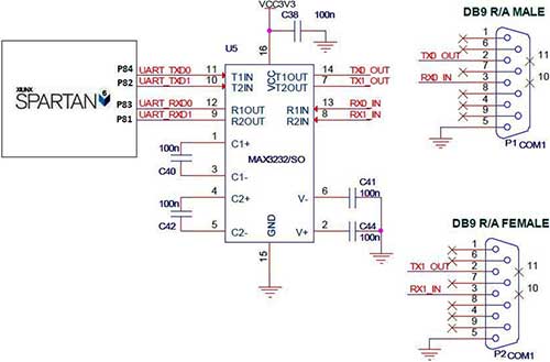
interfacing rs 232 with spartan 6 fpga
The UART (Universal Asynchronous Receiver/Transmitter) is a serial protocol featuring distinct transmit and receive lines, enabling full-duplex communication. The Spartan-6 board is equipped with two serial ports, as indicated in the accompanying figure. RS-232 serial communication is facilitated through a...
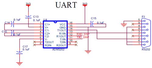
uart interfacing with blackfin tyro
The ADSP-BF533/32/31 processors are enhanced members of the Blackfin processor family that offer significantly higher performance and lower power consumption compared to previous Blackfin processors while maintaining ease of use and code compatibility. These processors are completely code and pin-compatible,...
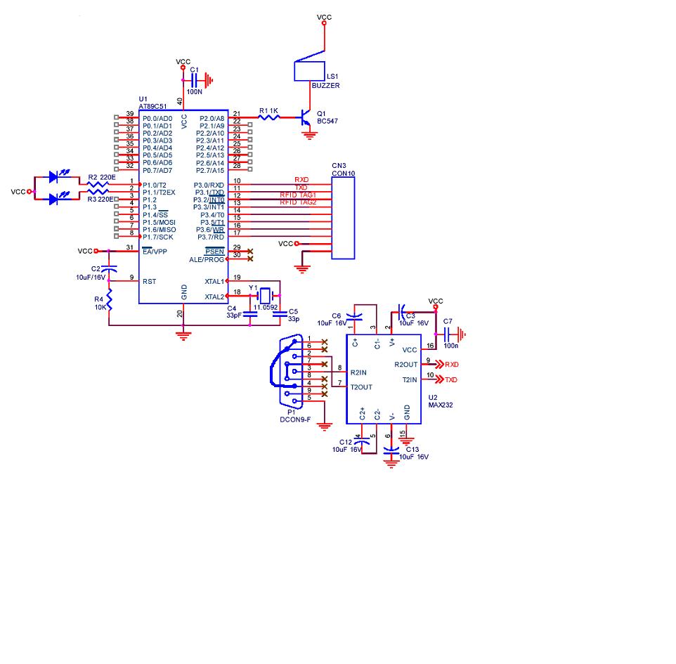
serial communication using UART in RFID project
A project is being developed utilizing RFID (Radio Frequency Identification) technology. The microcontroller chosen for this project is the AT89C51/52/S52. Serial communication is being implemented using RS-232.
The project involves the integration of RFID technology for identification and data exchange applications....
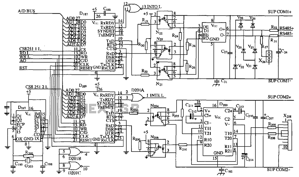
DK04 monitoring module with the computer communications interface circuits
As shown in the figure, D187 is a universal asynchronous receiver-transmitter (UART). Its RX/TX signals are received through optocouplers N21, N22, and N29, facilitating RS-485 communication. The interface receiver/transmitter D28 and microprocessor D211 are completely optically isolated. D197 serves as...
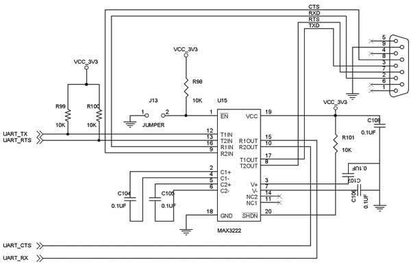
uart interfacing with tms320c5505 tyro
The TMS320C5505 Evaluation Board is specifically designed for developers in the DSP field as well as for beginners. The kit is structured in such a way that all possible features of the DSP can be easily utilized by everyone. UART...
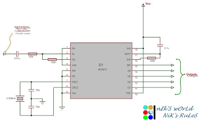
Microcontroller circuits
Connect the serial cable to the serial port. If using a USB to TTL, RS232, or serial converter, plug it into the USB port. Next, short the Tx pin to the Rx pin or the TxD pin to the RxD...
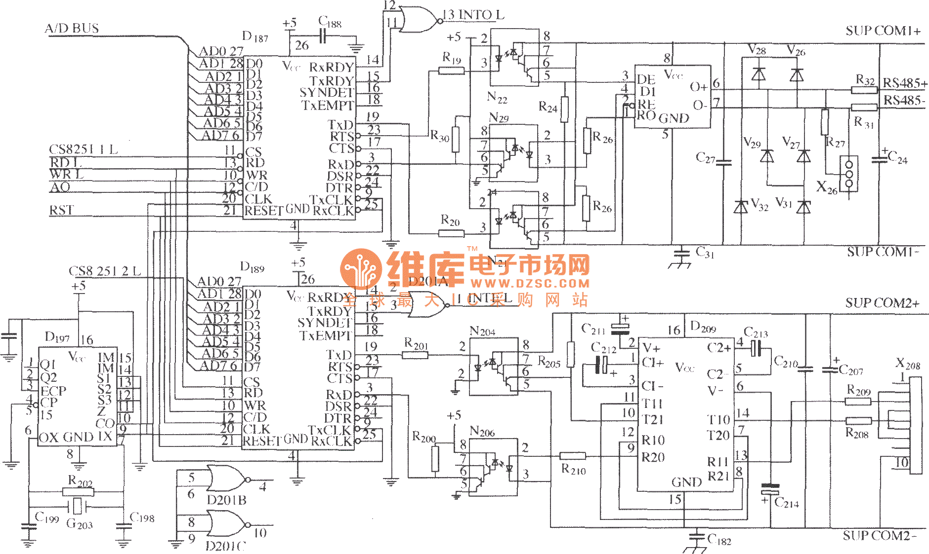
DK04 Monitoring Module and Computer communication interface circuit
As shown in the figure, D187 is a UART with its RX/TX signals connected through optocouplers N21, N22, and N29, providing complete optoelectronic isolation for the RS-485 communication interface receiver/transmitter D28 and microprocessor D211. D197 serves as a generator, and...
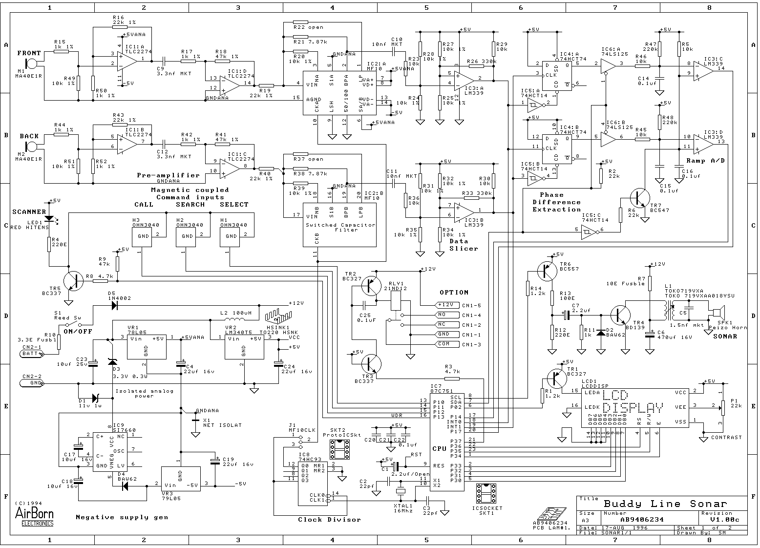
AirBorn Electronics project
Embedded system design engineers create examples of their work from the 1990s era.
Embedded systems have evolved significantly since the 1990s, and the design work from that period reflects the technological limitations and innovations of the time. Engineers in this field...
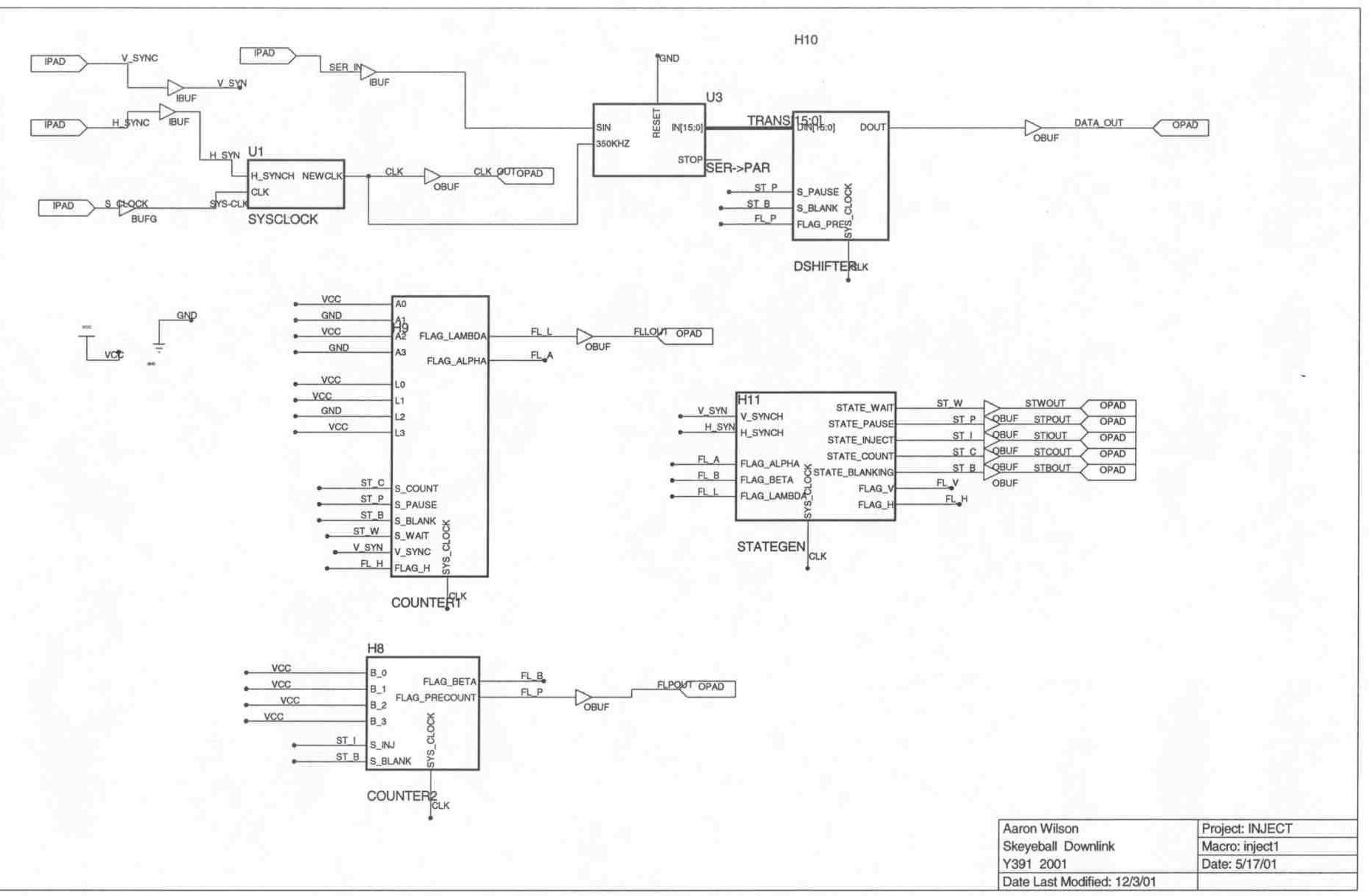
Downlink Project Description
The Skeyeball project is an ongoing initiative within the Indiana University System Design Methods Laboratory, aimed at providing graduate and undergraduate students with opportunities to engage in embedded system design and implement various projects. The downlink segment of the project...