


USB Switch For Printers circuit
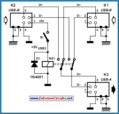
Description: This circuit switches a printer's USB connection from a PC to a laptop. The objective was to create a solution that enables a laptop to use the printer intermittently while maintaining the printer's primary connection to the PC. Instead of manually unplugging the printer from the PC and connecting it to the laptop, the circuit automatically switches the USB connection. K1 and K2 are standard type-B USB sockets, while K3 is a USB type-A socket.
The circuit utilizes a USB switch mechanism to facilitate seamless connectivity between a printer and two host devices, namely a PC and a laptop. The design incorporates two USB type-B sockets (K1 and K2) that serve as the input ports for the printer connection, allowing for the selection of either the PC or the laptop as the active host. The USB type-A socket (K3) connects to the printer, providing the necessary interface for communication.
The operation of the circuit is governed by a control logic that determines which USB socket is active based on user input or predefined conditions. This can be achieved using a simple toggle switch, push button, or automated control via a microcontroller, depending on the desired functionality. When the user wishes to switch from one device to another, the control logic activates the appropriate relay or electronic switch to redirect the USB data lines and power lines accordingly.
In terms of electrical characteristics, the circuit must ensure that it adheres to USB specifications to maintain data integrity and power delivery. This includes managing the 5V power supply to the printer and ensuring that the data lines (D+ and D-) are correctly routed without introducing interference or signal degradation.
Overall, this USB switching circuit provides an efficient solution for managing printer connectivity between multiple devices, enhancing user convenience and reducing wear on physical connections. The design can be further optimized by incorporating features such as LED indicators to show which device is currently connected, and additional protection circuitry to prevent potential damage from incorrect connections.This circuit switches a printer s USB connection from a PC to a laptop. What was needed was a method of allowing a laptop to use the printer occasionally while at all other times the printer would be connected to the PC. Instead of unplugging the printer from the PC and then into the laptop, the circuit switches the USB connection automatically.
K1 and K2 are standard type-B USB sockets, while K3 is a USB type-A socket..
The circuit utilizes a USB switch mechanism to facilitate seamless connectivity between a printer and two host devices, namely a PC and a laptop. The design incorporates two USB type-B sockets (K1 and K2) that serve as the input ports for the printer connection, allowing for the selection of either the PC or the laptop as the active host. The USB type-A socket (K3) connects to the printer, providing the necessary interface for communication.
The operation of the circuit is governed by a control logic that determines which USB socket is active based on user input or predefined conditions. This can be achieved using a simple toggle switch, push button, or automated control via a microcontroller, depending on the desired functionality. When the user wishes to switch from one device to another, the control logic activates the appropriate relay or electronic switch to redirect the USB data lines and power lines accordingly.
In terms of electrical characteristics, the circuit must ensure that it adheres to USB specifications to maintain data integrity and power delivery. This includes managing the 5V power supply to the printer and ensuring that the data lines (D+ and D-) are correctly routed without introducing interference or signal degradation.
Overall, this USB switching circuit provides an efficient solution for managing printer connectivity between multiple devices, enhancing user convenience and reducing wear on physical connections. The design can be further optimized by incorporating features such as LED indicators to show which device is currently connected, and additional protection circuitry to prevent potential damage from incorrect connections.This circuit switches a printer s USB connection from a PC to a laptop. What was needed was a method of allowing a laptop to use the printer occasionally while at all other times the printer would be connected to the PC. Instead of unplugging the printer from the PC and then into the laptop, the circuit switches the USB connection automatically.
K1 and K2 are standard type-B USB sockets, while K3 is a USB type-A socket..

ZX-Printer Service Manual
This manual is intended for use by authorized Sinclair dealers, engineers, and representatives as a guide for rectifying faults in the Sinclair ZX Printer. Repair and renewal procedures are limited to those specific to this printer; standard procedures for renewing...
Laptop Notebook Schematic
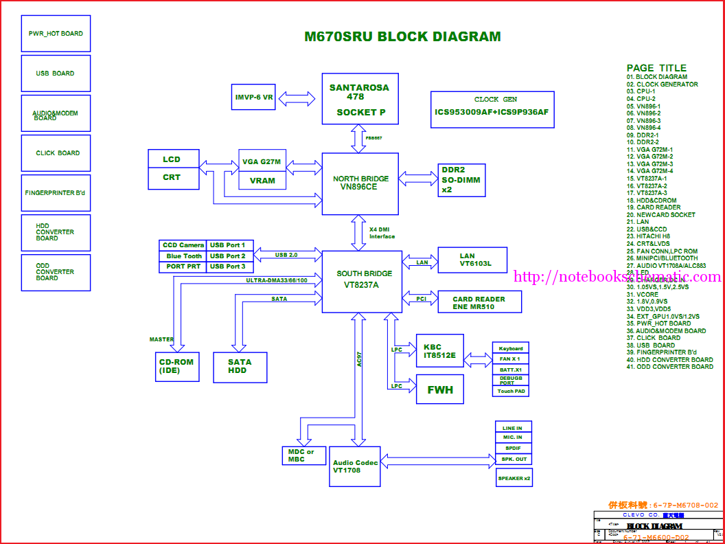
Laptop schematic circuit diagram for laptop repair and laptop BIOS password removal.
The laptop schematic circuit diagram serves as a critical resource for technicians involved in laptop repair. This diagram provides a comprehensive representation of the electronic components and their interconnections...
stand by detector
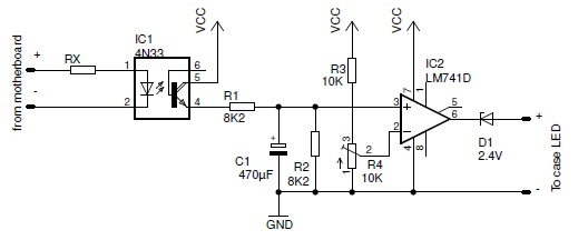
The PC Standby Detector is a compact circuit designed to deactivate the power LED when the PC enters standby mode.
The PC Standby Detector circuit functions by monitoring the power state of the computer. When the computer is in standby mode,...
always on for pcs circuit
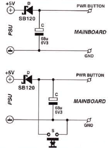
Many enthusiasts utilize their PCs as data loggers, controllers, or web servers. In such instances, it is crucial to ensure that the machine remains powered for as much time as possible, even during a power outage or if the power...
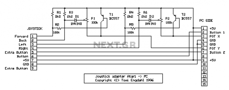
PC joystick interface circuits
NOTE: There is no guarantee as to the suitability of said circuits and information for any purpose whatsoever other than as a self-training aid. I.E. If it blows your equipments, trashes your hard disc, wipes your backup, burns your building...
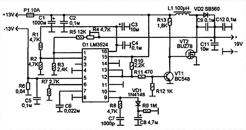
Laptop Power Supply for Car Schematic Diagram
Laptops, commonly referred to as notebook computers, have gained significant popularity. Their portable design allows them to be easily transported in a bag, making them suitable for business trips and serving as convenient home entertainment centers due to their compact...
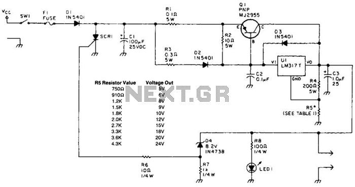
Laptop Computer Power Supply Circuit
A laptop computer power supply that provides a 9-V output, includes crowbar overvoltage protection, and operates from a 12-V input supply is described. The input supply voltage must be at least 3.6 V above the desired output voltage. The transistor...
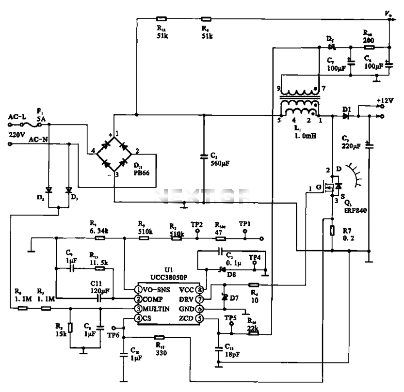
A typical laptop power adapter circuit
A typical laptop power adapter circuit converts an AC input of 22V through a rectifier and filter circuit to produce an output of +30V DC. This voltage is then processed by a switch oscillation circuit (U1, UCC38050P), which controls the...
start up aid for pcs
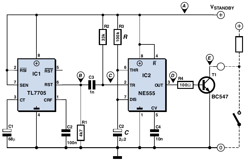
The older PC in question has a standby state but lacks a corresponding BIOS setting to enable unattended startup. Although a +5 V standby supply voltage is present, the computer requires a brief push of a button to power on....