


4011 dual led flasher
#4011
#NAND gate
#LED flasher
#capacitor
#decoupling capacitor
#flashing circuit
#Quad IC
#simple circuit
#alternate flashing
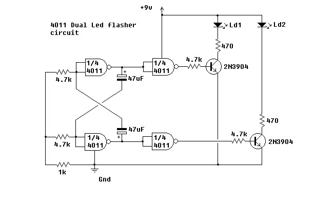
Description: This simple circuit utilizes NAND gates to alternately flash two LEDs. The two 47µF capacitors set the flashing frequency. It is advisable to include a decoupling capacitor across the power supply. The circuit was constructed using the specified components and functioned correctly. The integrated circuit used is the 4011 Quad.
The circuit design employs a 4011 Quad NAND gate integrated circuit, which contains four independent NAND gates. The configuration is designed to create a bistable multivibrator or flip-flop arrangement that alternates the state of two LEDs, resulting in a blinking effect. The two 47µF capacitors are pivotal in determining the timing characteristics of the circuit. These capacitors, in conjunction with the resistors (not specified in the description but typically included in such circuits), establish the charge and discharge cycles that control the frequency of the LED flashing.
A decoupling capacitor should be placed across the power supply terminals of the 4011 IC to filter out any noise and stabilize the voltage supply, ensuring reliable operation of the circuit. This capacitor typically has a value of 0.1µF and is placed as close as possible to the power pins of the IC.
To construct the circuit, each NAND gate is configured to create a feedback loop, where the output of one gate is connected to the input of another. This arrangement allows for the alternation of the output states, causing one LED to turn on while the other turns off, and vice versa. The timing of the LED flashes can be adjusted by varying the capacitance of the 47µF capacitors or by changing the associated resistors in the circuit.
In summary, the circuit effectively demonstrates the use of NAND gates for creating an alternating LED flash effect, highlighting the fundamental principles of digital electronics and timing circuits. Proper component selection and configuration are crucial for achieving the desired operational characteristics.This simple circuit uses NAND Gates to alternately flash two led`s. The two 47uF capacitors determine the flash frequency. It is a good idea to use a decoupling capacitor across the power supply. I made this circuit using the components shown and it worked fine. The IC that I used is the 4011 Quad
The circuit design employs a 4011 Quad NAND gate integrated circuit, which contains four independent NAND gates. The configuration is designed to create a bistable multivibrator or flip-flop arrangement that alternates the state of two LEDs, resulting in a blinking effect. The two 47µF capacitors are pivotal in determining the timing characteristics of the circuit. These capacitors, in conjunction with the resistors (not specified in the description but typically included in such circuits), establish the charge and discharge cycles that control the frequency of the LED flashing.
A decoupling capacitor should be placed across the power supply terminals of the 4011 IC to filter out any noise and stabilize the voltage supply, ensuring reliable operation of the circuit. This capacitor typically has a value of 0.1µF and is placed as close as possible to the power pins of the IC.
To construct the circuit, each NAND gate is configured to create a feedback loop, where the output of one gate is connected to the input of another. This arrangement allows for the alternation of the output states, causing one LED to turn on while the other turns off, and vice versa. The timing of the LED flashes can be adjusted by varying the capacitance of the 47µF capacitors or by changing the associated resistors in the circuit.
In summary, the circuit effectively demonstrates the use of NAND gates for creating an alternating LED flash effect, highlighting the fundamental principles of digital electronics and timing circuits. Proper component selection and configuration are crucial for achieving the desired operational characteristics.This simple circuit uses NAND Gates to alternately flash two led`s. The two 47uF capacitors determine the flash frequency. It is a good idea to use a decoupling capacitor across the power supply. I made this circuit using the components shown and it worked fine. The IC that I used is the 4011 Quad
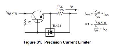
Capacitor Charging Circuit
This Korean SuperCap OEM supports usage in series configurations. Consider whether the implementation will be manual or automatic, such as with a smart battery charger or a power fail backup circuit. It is essential to balance the voltage and provide...
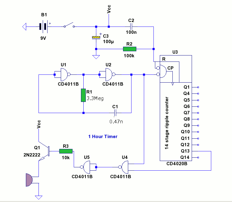
1 hour timer circuit with 4011 and 4020 ICs
This circuit utilizes two CMOS ICs: a 4011 quad 2-input NAND gate and a 4020 14-stage ripple binary counter. Upon powering on, resistors R2 and capacitor C2 generate a brief reset pulse, ensuring that the output pin Q1 of the...
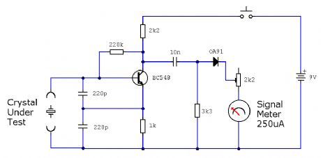
ELF MONITOR
The capacitor instrument is not intended for measuring the capacitance of capacitors; rather, it is designed to identify whether a capacitor is functional or defective, as well as to detect short circuits or open circuits. This functionality provides reliable quality...

Capacitor step-down DC power supply circuit
A capacitor step-down DC power supply circuit is presented. This circuit eliminates the need for power transformers, utilizing capacitive voltage drop rectification and regulation, which significantly reduces the overall size of the circuit. The circuit includes a capacitor step-down component,...
ELF MONITOR
The capacitor instrument is not intended for measuring the capacitance of capacitors; rather, it is designed to identify whether a capacitor is functional or defective, as well as to detect short circuits or open circuits. This functionality provides reliable quality...
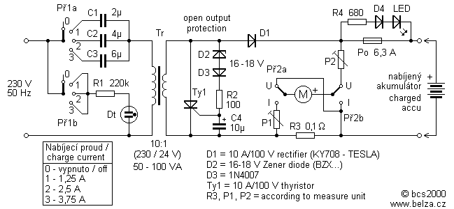
Capacitor Charger Lead Acid Battery
Leaving aside the complex chargers, "stuffed" electronics capacitor charger is one of the best connections. Charging current is limited by the resistor (or other element of the changing excess energy into heat), but the reactance of the capacitor to the...
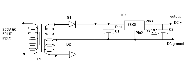
Power supply circuit design
C1 is a 1000 microfarad aluminum electrolytic capacitor. For loads less than 100mA, a 220 microfarad capacitor can be substituted. The voltage rating should be 2.5 times the output voltage.
C1 serves as a critical component in various electronic circuits, particularly...
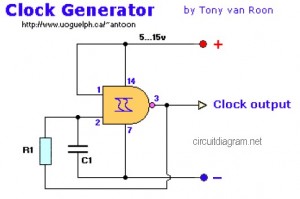
NAND Gate Clock Generator circuit diagram
The following diagram represents a Clock Generator circuit that is constructed using NAND Gate logic integrated circuits (ICs). The circuit can utilize either IC 7400 or IC 4011. The 7400 is a TTL (Transistor-Transistor Logic) type, whereas the 4011 is...
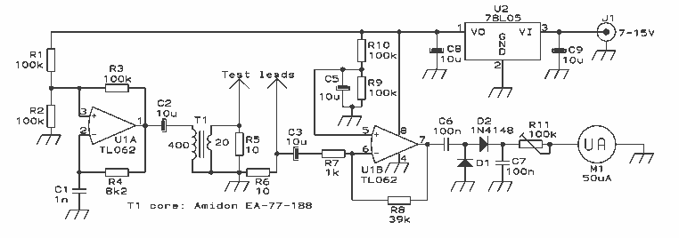
Capacitor internal resistor meter
The design presented here works by applying a 50kHz, 200mV square wave to the capacitor under test, in series with a 10 Ohm resistor. The AC voltage appearing across that resistor is measured and displayed on a meter. So the...