


A digital display clock signal source CD4543 CD4060 CD4518
#CD4543
#CD4060
#CD4518
#clock signal
#digital display
#multipoint detection
#control box
#timing circuit
#counter
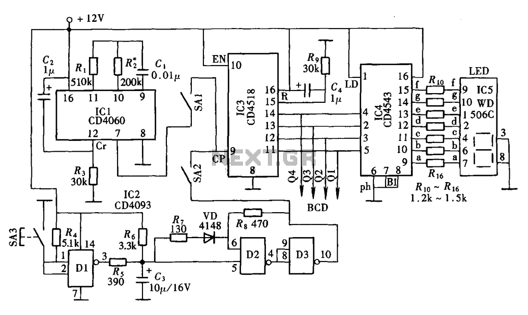
Description: The digital display clock signal source circuit depicted in the figure is derived from a multi-point detection control box within the actual circuit. It primarily comprises an automatic and manual pulse generator, a clock pulse generator, pulse counting elements, and digital display components.
The digital display clock signal source circuit serves as a critical component in various electronic systems, providing accurate timing signals that can be utilized for synchronization and control purposes. The circuit's architecture typically involves two main types of pulse generators: an automatic pulse generator that continuously produces clock pulses at a predefined frequency, and a manual pulse generator that allows for user-defined pulse generation.
The automatic pulse generator usually employs a stable oscillator circuit, which may consist of a 555 timer or a crystal oscillator, ensuring reliable and consistent clock signals. The output of this generator feeds into a pulse counting mechanism, which counts the number of pulses over a specified time interval. This counting function is essential for applications requiring precise time measurement or event counting.
The manual pulse generator may incorporate switches or buttons that enable the user to initiate pulse generation on demand. This feature is particularly useful in testing scenarios or when specific timing events need to be triggered manually.
The pulse counting components may include flip-flops or counters that register the incoming pulses and convert them into a format suitable for display. The digital display components, often based on LED or LCD technology, present the counted pulses in a human-readable format, allowing users to monitor the timing signals easily.
Overall, this digital display clock signal source circuit integrates various electronic elements to create a versatile timing solution, suitable for applications ranging from simple timing tasks to complex control systems.Digital display clock signal source circuit shown in the figure is taken from a multi-point detection control box in the actual circuit. It mainly consists of automatic and man ual pulse generator clock pulse generator, pulse counting and digital display components.
The digital display clock signal source circuit serves as a critical component in various electronic systems, providing accurate timing signals that can be utilized for synchronization and control purposes. The circuit's architecture typically involves two main types of pulse generators: an automatic pulse generator that continuously produces clock pulses at a predefined frequency, and a manual pulse generator that allows for user-defined pulse generation.
The automatic pulse generator usually employs a stable oscillator circuit, which may consist of a 555 timer or a crystal oscillator, ensuring reliable and consistent clock signals. The output of this generator feeds into a pulse counting mechanism, which counts the number of pulses over a specified time interval. This counting function is essential for applications requiring precise time measurement or event counting.
The manual pulse generator may incorporate switches or buttons that enable the user to initiate pulse generation on demand. This feature is particularly useful in testing scenarios or when specific timing events need to be triggered manually.
The pulse counting components may include flip-flops or counters that register the incoming pulses and convert them into a format suitable for display. The digital display components, often based on LED or LCD technology, present the counted pulses in a human-readable format, allowing users to monitor the timing signals easily.
Overall, this digital display clock signal source circuit integrates various electronic elements to create a versatile timing solution, suitable for applications ranging from simple timing tasks to complex control systems.Digital display clock signal source circuit shown in the figure is taken from a multi-point detection control box in the actual circuit. It mainly consists of automatic and man ual pulse generator clock pulse generator, pulse counting and digital display components.
timing circuit
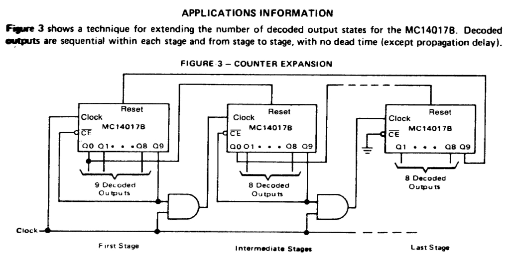
Assistance is needed for the design of a timing circuit intended to activate a spark plug every 10 or 20 revolutions of a shaft.
The timing circuit for firing a spark plug at specified intervals can be designed using a combination...
1Hz Timebase For Readout And Counter Applications
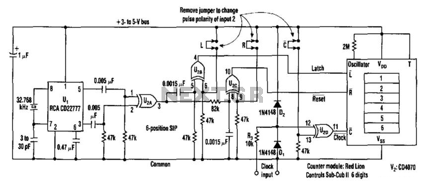
This counter facilitates the direct readout of frequency-generating equipment by incorporating a 1-Hz time base to latch, reset, and condition the count signal. The design allows for the selection of either polarity. By differentiating, inverting, and ORing the clock pulses...
PSIM Training CD-ROMs
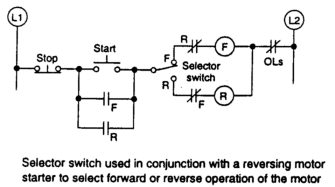
The counter is programmed to function in a batch-counting operation, automatically sorting parts for quality control. It is designed to divert one part out of every ten for the quality control or inspection process. The circuit operates as described.
The automatic...
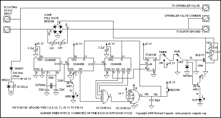
Garden timer circuit with CD4000
The resulting timer circuit is made from a CD4060, includes an oscillator and a 14 stage binary counter, two CD4040's, which are 12 stage binary counters, a CD4012 Dual Nand gate and a CD4013 Dual D Latch. The CD4060 is...
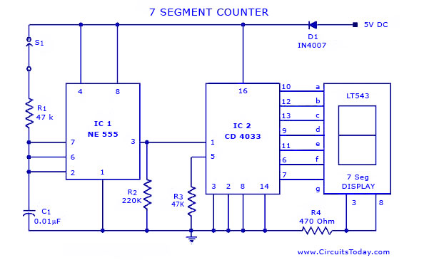
Seven-7-Segment Counter Circuit with LED Display-Diagram and Schematic
A simple seven-segment counter circuit with an LED display. This counter circuit diagram is designed using the IC CD 4033 as a counter, a 555 Timer IC, and a seven-segment LED display LT 543.
The seven-segment counter circuit utilizes the CD...
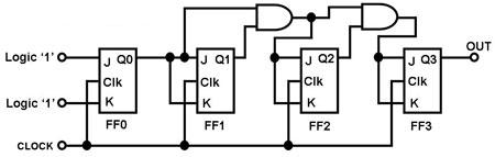
digital counter circuits
The circuit in Figure 1 is a 4-bit asynchronous counter, also known as a ripple counter. It consists of four J-K flip-flops with their J and K inputs connected to logic 1. This configuration causes the output of each J-K...
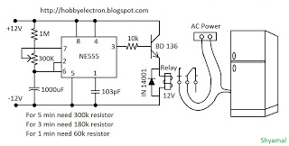
freeze protector circuit
This is a simple freeze protector circuit diagram, also known as a timing circuit. It serves as a hobby project for beginners. This circuit can automatically operate any device after a fixed time once AC power supply is restored. The...
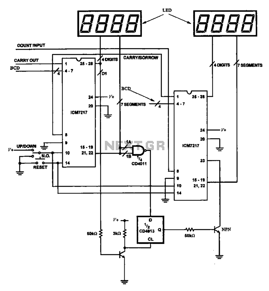
8-bit digital counter circuit
Figure 8 illustrates a potential digital counter circuit. This circuit employs two ICM7217 integrated circuits, with each controlling four digital display tubes.
The digital counter circuit primarily utilizes the ICM7217, a highly integrated chip designed for driving seven-segment displays. Each ICM7217...
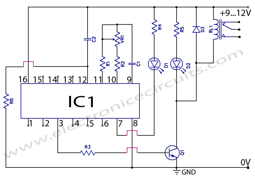
CD4060 Timer Circuit 1 minute to 2 hours
CD4060 Timer Circuit 1 minute to 2 hours This is a 1 minute to two-hour timer switch. The 14-stage binary ripple counter Type 4060, IC1, has an...
The CD4060 timer circuit is designed to function as a timer switch with a...