


Bistable circuit at the operating frequency of 10kHz or less
#bistable
#flip-flop
#frequency
#10kHz
#logic circuit
#digital
#timing
#signal
#electronics
#schematic
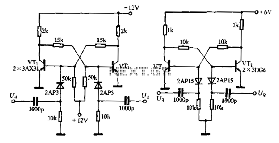
Description: Bistable circuit operating at a frequency of 10 kHz or lower.
A bistable circuit, also known as a flip-flop, is a fundamental building block in digital electronics. It has two stable states and can store one bit of data. The circuit can be triggered to switch between these states using input signals. In this case, the bistable circuit is designed to operate at a frequency of 10 kHz or lower, making it suitable for applications that require low-speed data processing and control.
The bistable circuit typically consists of two main components: the input stage and the output stage. The input stage accepts control signals, which can be in the form of clock pulses or other digital signals. These input signals determine the state transitions of the circuit. The output stage provides the stored data, which reflects the current state of the bistable circuit.
Common implementations of bistable circuits include SR (Set-Reset) flip-flops, JK flip-flops, and D (Data) flip-flops. Each type has distinct characteristics and applications. For instance, the SR flip-flop is triggered by the set and reset inputs, while the JK flip-flop allows for toggling between states based on the clock signal. The D flip-flop captures the value of the input signal at the moment of the clock edge, making it ideal for data storage.
In practical applications, bistable circuits are utilized in memory storage, digital counters, and control systems. The ability to operate at frequencies of 10 kHz or lower ensures compatibility with various low-speed digital systems, enhancing reliability and performance in applications such as timers, state machines, and simple data latches. Proper design considerations, including component selection and power supply stability, are essential to ensure optimal functioning of the bistable circuit in its intended application. Bistable circuit at the operating frequency of 10kHz or less
A bistable circuit, also known as a flip-flop, is a fundamental building block in digital electronics. It has two stable states and can store one bit of data. The circuit can be triggered to switch between these states using input signals. In this case, the bistable circuit is designed to operate at a frequency of 10 kHz or lower, making it suitable for applications that require low-speed data processing and control.
The bistable circuit typically consists of two main components: the input stage and the output stage. The input stage accepts control signals, which can be in the form of clock pulses or other digital signals. These input signals determine the state transitions of the circuit. The output stage provides the stored data, which reflects the current state of the bistable circuit.
Common implementations of bistable circuits include SR (Set-Reset) flip-flops, JK flip-flops, and D (Data) flip-flops. Each type has distinct characteristics and applications. For instance, the SR flip-flop is triggered by the set and reset inputs, while the JK flip-flop allows for toggling between states based on the clock signal. The D flip-flop captures the value of the input signal at the moment of the clock edge, making it ideal for data storage.
In practical applications, bistable circuits are utilized in memory storage, digital counters, and control systems. The ability to operate at frequencies of 10 kHz or lower ensures compatibility with various low-speed digital systems, enhancing reliability and performance in applications such as timers, state machines, and simple data latches. Proper design considerations, including component selection and power supply stability, are essential to ensure optimal functioning of the bistable circuit in its intended application. Bistable circuit at the operating frequency of 10kHz or less
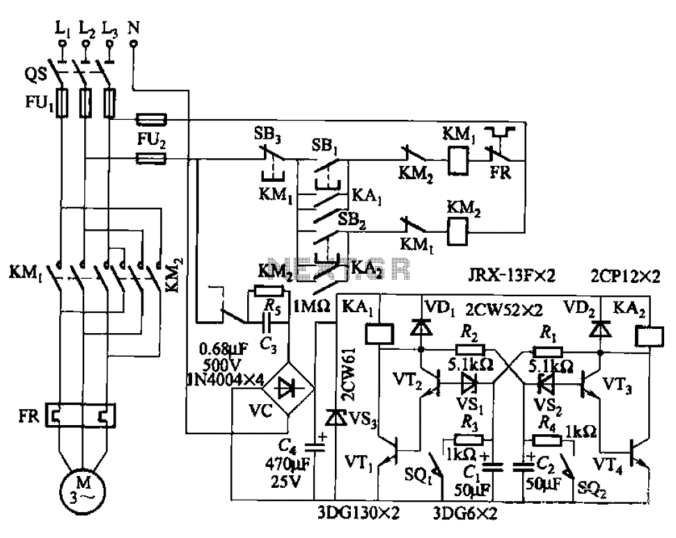
Bistable circuit control motor reversing circuit
The circuit illustrated in Figure 3-72 employs a deformable bistable reversing motor control mechanism that automatically initiates and halts operation during a user-defined time delay. This feature is designed to safeguard the motor from potential impacts during the reversing transition....
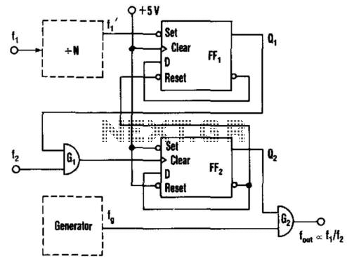
Frequency-Ratio Monitoring Circuit
This circuit generates an output frequency that is linearly proportional to the ratio of two input frequencies. Each pulse of the bias frequency will open a switch for a period equal to half of the second input frequency, allowing a...
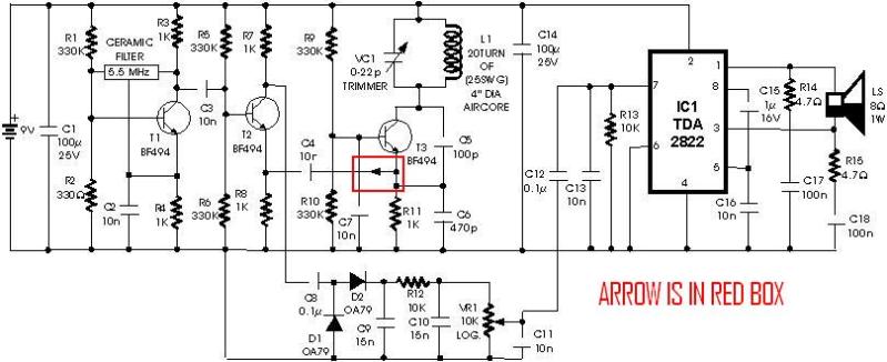
metal detector project circuit
A schematic diagram for a metal detector has been found. The project does not need to be original and can be sourced from the internet. There are several questions regarding this schematic. One query pertains to a small arrow connected...
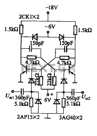
Practical flip-flop circuit
A flip-flop circuit with a memory function for pulse signals. It features two stable states: one where transistor VTi is off and VTZ is conducting, and another where VTi is conducting and VT2 is off. An external signal is sufficient...
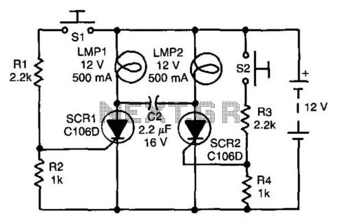
Flip-Flop Independent Lamp Driver
Assume first that SCR1 is on and SCR2 is off, allowing capacitor CI to be fully charged, with its LMP2 end positive. The state of the circuit can be altered by pressing switch S2. When SCR2 turns on, it capacitively...
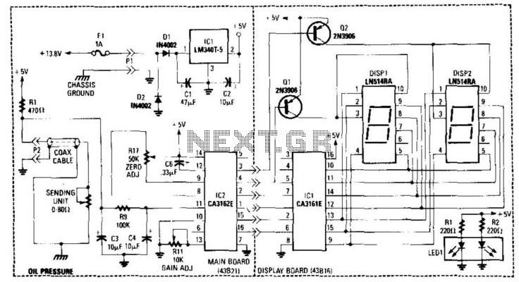
Digital Oil-Pressure Gauge
This gauge utilizes a sensor along with resistor R1 to generate a DC voltage that is proportional to oil pressure. Integrated circuits IC1 and IC2 form a two-digit digital voltmeter (DVM). Transistors Q1 and Q2 act as display selectors for...
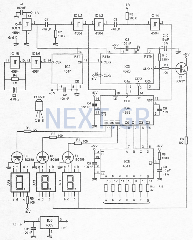
High Precision Digital Pulse Meter Circuit
This compact device, designed primarily for modelers, provides instantaneous readings of pulse duration in milliseconds (ms). It can measure servomotor positions, typically ranging from 1 ms to 2 ms, and can also perform repetitive or non-pulsed measurements, such as the...
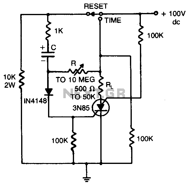
Timing circuit
Load current starts approximately 0 RC after the switch is thrown.
The statement indicates that the load current begins at approximately 0 ohms after a switch is activated. This scenario is common in electronic circuits where a switch controls the flow...
Homemade Digital CALL-ID English Version
The reason for this project was to facilitate a quick installation for a local friend 10 km away, enabling the start of real-life testing to identify and resolve bugs and problems before releasing it to other users. The software is...