


controller 4017 counter LEDs have multiple connections in this traffic light circuit
#4017 counter
#LED
#traffic light
#wired-OR
#digital logic
#timing
#sequential circuit
#output control
#counter IC
#light control
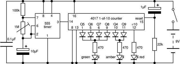
Description: The 4017 traffic light circuit connects four legs to the green LED and two legs to the amber LED. This configuration raises the question of whether it could function with only one leg per LED. Each output is activated consecutively for an equal duration. By implementing wired-OR logic on the outputs, extended active times can be achieved. Consequently, the green LED remains illuminated for four time units. Typically, one would need to wire-OR outputs Q0 through Q4 for the red LED; however, a carry output, referred to as ":10", accomplishes this task, as illustrated in the lower trace of the timing diagram.
The 4017 decade counter is widely utilized in timing and sequencing applications, such as traffic light control systems. In this circuit, the green LED is connected to outputs Q0, Q1, Q2, and Q3, allowing it to remain on for a cumulative duration of four time units. This is achieved through a wired-OR connection, which effectively combines multiple outputs into a single active state. The result is an extended illumination period for the green LED, which is essential for traffic management.
The amber LED is connected to outputs Q4 and Q5, indicating a transitional state between green and red. This setup ensures that the amber light activates for a shorter duration, signaling drivers to prepare to stop. The use of two legs for the amber LED allows for a more reliable, brighter signal compared to a single connection.
The carry output, denoted as ":10", serves a critical role in the operation of the red LED. By linking the outputs Q0 through Q4, the circuit can effectively manage the timing of the red light, ensuring it remains illuminated for the necessary duration to allow vehicles to stop safely. The design of the circuit is carefully calibrated to reflect standard traffic light sequences, enhancing road safety and efficiency.
In summary, the 4017 traffic light circuit employs a strategic connection of multiple outputs to control the LEDs, utilizing both wired-OR configurations and carry outputs to optimize the timing and visibility of the traffic signals. This design not only meets functional requirements but also adheres to established traffic management protocols.Why are four legs connected to the green LED and two to the amber LED in the 4017 traffic light circuit Shouldn`t it be able to do with only one leg per LED Each output is consecutively active for the same time. By wired-OR-ing outputs you can create longer active times. So the green LED will be on during 4 time units. Normally you would have to wired-OR Q0 through Q4 for the red LED, but we have a carry output (here called ":10") which does just that, see the bottom trace of the timing diagram:
The 4017 decade counter is widely utilized in timing and sequencing applications, such as traffic light control systems. In this circuit, the green LED is connected to outputs Q0, Q1, Q2, and Q3, allowing it to remain on for a cumulative duration of four time units. This is achieved through a wired-OR connection, which effectively combines multiple outputs into a single active state. The result is an extended illumination period for the green LED, which is essential for traffic management.
The amber LED is connected to outputs Q4 and Q5, indicating a transitional state between green and red. This setup ensures that the amber light activates for a shorter duration, signaling drivers to prepare to stop. The use of two legs for the amber LED allows for a more reliable, brighter signal compared to a single connection.
The carry output, denoted as ":10", serves a critical role in the operation of the red LED. By linking the outputs Q0 through Q4, the circuit can effectively manage the timing of the red light, ensuring it remains illuminated for the necessary duration to allow vehicles to stop safely. The design of the circuit is carefully calibrated to reflect standard traffic light sequences, enhancing road safety and efficiency.
In summary, the 4017 traffic light circuit employs a strategic connection of multiple outputs to control the LEDs, utilizing both wired-OR configurations and carry outputs to optimize the timing and visibility of the traffic signals. This design not only meets functional requirements but also adheres to established traffic management protocols.Why are four legs connected to the green LED and two to the amber LED in the 4017 traffic light circuit Shouldn`t it be able to do with only one leg per LED Each output is consecutively active for the same time. By wired-OR-ing outputs you can create longer active times. So the green LED will be on during 4 time units. Normally you would have to wired-OR Q0 through Q4 for the red LED, but we have a carry output (here called ":10") which does just that, see the bottom trace of the timing diagram:
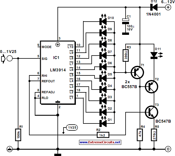
LED Bar Off Indicator
The simple indicator described in this article can be integrated with any circuit that features an LED bar display powered by a Type LM3914 IC. It ensures that an LED will illuminate when all LEDs driven by the LM3914 are...
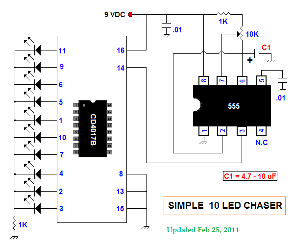
led chasers
This summer, several LED projects were constructed, including sequential LED chasers that operate from left to right and a Nite-Rider style that moves sequentially left, right, left, right, and so on. These projects are enjoyable for children to experiment with....
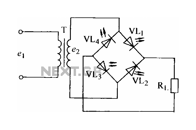
Light-emitting diode rectifier circuit
In certain applications, the current from a non-rectified voltage power supply circuit is insufficient. A light-emitting diode (LED) rectifier circuit can be employed to address this issue, serving as a power indicator. It is important to ensure that the forward...
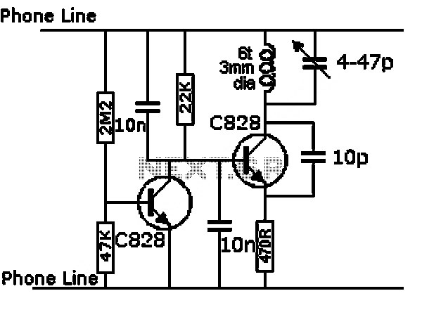
led photo sensor circuit
This design outlines a sensor circuit that utilizes an LED as a light sensor. The operational control and amplification of the output are managed by a 1458 integrated circuit (IC), which functions as an operational amplifier (op-amp). The circuit exploits...
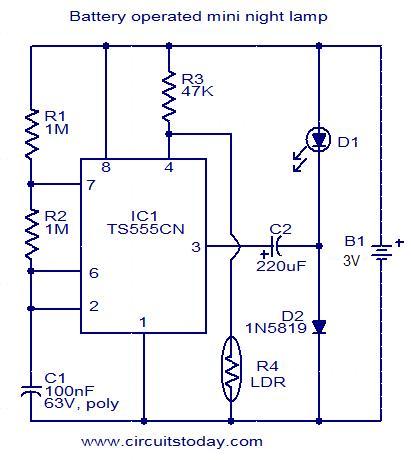
Battery operated mini night lamp
This circuit is designed as a low-power LED night lamp that automatically switches off during daytime. The CMOS timer IC TS555CN is configured as a square wave generator operating at approximately 5 Hz. The output voltage from the IC is...
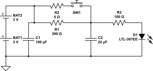
Motion sensing LED Quantum Bits
The circuit operates as follows: The LED is typically powered at a low brightness through resistors R1 and R3. SW1 functions as a spring and wire-based accelerometer. When SW1 is activated, capacitor C2 charges rapidly at a rate determined by...
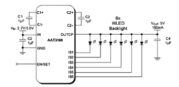
Drive Two-Six White LEDs (WLEDs) in Parallel
The parallel arrangement of LED backlights allows the control IC to utilize inexpensive low voltage CMOS processes, as illustrated in the following circuit diagram, which requires two to six white LEDs (WLEDs) in parallel. In many applications, LED backlights are...
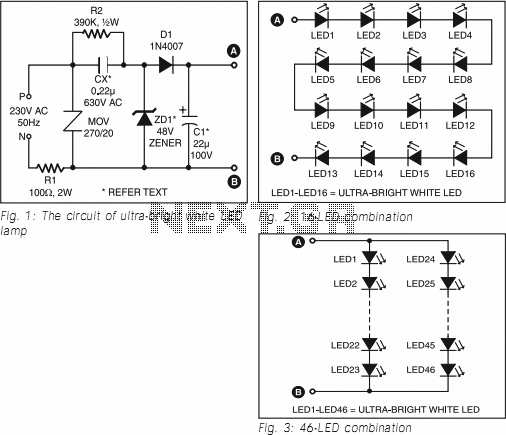
Ultra Bright LED Lamp
This ultra-bright white LED lamp operates on 230V AC with minimal power consumption. It is suitable for illuminating VU meters, SWR meters, and similar applications. Ultra-bright LEDs available in the market are priced between Rs 8 to 15. These LEDs...
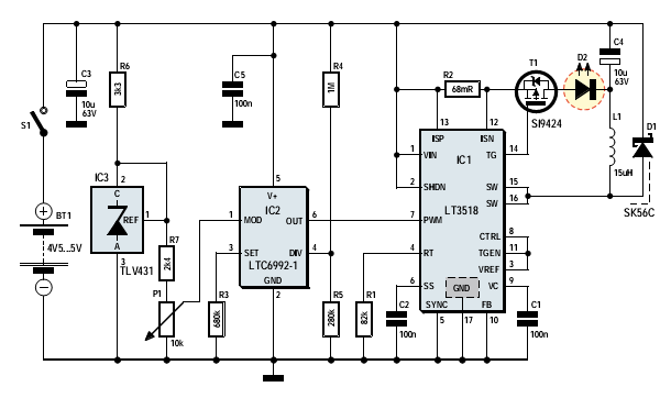
power led driver
More:
A comprehensive electronic schematic involves the representation of electrical components and their interconnections in a circuit. Each component is typically represented by standardized symbols, and the connections between them are depicted using lines. The schematic provides essential information for...