


Digital Clock circuit with CMOS 4047
#digital clock
#CMOS 4047
#square wave
#multivibrator
#binary counters
#Tom Duncan
#low-power
#monostable
#astable
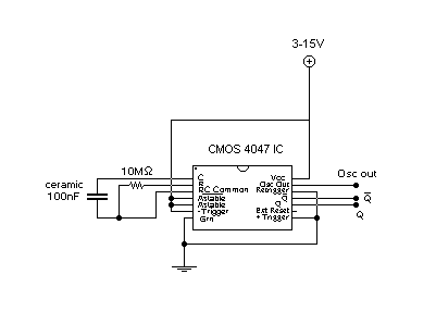
Description: This circuit provides a digital square wave that can be viewed directly or used to drive other circuits. It used the CMOS 4047 Low-Power Monostable/Astable Multivibrator. As used in Tom Duncan's Adventures with Digital Electronics Book, to drive CMOS Decade of 4-bit binary counters. More: RC = 10M x 100nF = (10x106) x (100x10-9) = 1 Hz OscOut (Double Frequency of Q) Q (Inverse of Q) Q (Square Wave, Frequency RC Hz, 1:1 Mark:Space Ratio) These 3 outputs can be viewed using an LED and 330R Resistor in series. 4047 Low-power astable/monostable multivibrator with oscillator output.
The described circuit utilizes the CMOS 4047, a versatile low-power monostable and astable multivibrator, to generate a digital square wave signal. This square wave can be employed for various applications, including driving other digital circuits or visual indicators like LEDs.
In the astable mode of operation, the 4047 generates a continuous square wave output. The frequency of this output is determined by the resistor-capacitor (RC) time constant, where the resistor (R) is set to 10 MΩ and the capacitor (C) is set to 100 nF. The calculated frequency of the square wave output is approximately 1 Hz, as derived from the formula \( f = \frac{1}{2 \cdot R \cdot C} \). This frequency corresponds to a duty cycle of 50%, resulting in a 1:1 mark-to-space ratio in the output waveform.
The 4047 provides multiple outputs: the primary output (Q), its inverse (notated as Q'), and an oscillator output (OscOut), which operates at double the frequency of the Q output. The Q output represents the square wave signal, while Q' provides the inverted square wave. The OscOut serves as a higher frequency alternative, suitable for applications requiring a faster signal.
To visualize the outputs, an LED can be connected in series with a 330 Ω resistor. This arrangement allows for direct observation of the square wave signal, with the LED turning on and off in accordance with the output frequency. The resistor is essential to limit the current flowing through the LED, protecting it from excess current that could lead to damage.
Overall, the CMOS 4047 multivibrator circuit is a practical solution for generating square wave signals, applicable in various electronic projects and systems requiring timing or waveform generation.This circuit provides a digital square wave that can be viewed directly or used to drive other circuits. It used the CMOS 4047 Low-Power Monostable/Astable Multivibrator. As used in Tom Duncan's Adventures with Digital Electronic's Book, to drive CMOS Decade of 4-bit binary counters.
RC = 10M x 100nF = (10x106) x (100x10-9) = 1 Hz OscOut (Double Frequency of Q) _ Q (Inverse of Q) Q (Square Wave, Frequency RC Hz, 1:1 Mark:Space Ratio) These 3 outputs can be viewed using an LED and 330R Resitor in series. 4047 Low-power astable/monostable multivibrator with oscillator output.
The described circuit utilizes the CMOS 4047, a versatile low-power monostable and astable multivibrator, to generate a digital square wave signal. This square wave can be employed for various applications, including driving other digital circuits or visual indicators like LEDs.
In the astable mode of operation, the 4047 generates a continuous square wave output. The frequency of this output is determined by the resistor-capacitor (RC) time constant, where the resistor (R) is set to 10 MΩ and the capacitor (C) is set to 100 nF. The calculated frequency of the square wave output is approximately 1 Hz, as derived from the formula \( f = \frac{1}{2 \cdot R \cdot C} \). This frequency corresponds to a duty cycle of 50%, resulting in a 1:1 mark-to-space ratio in the output waveform.
The 4047 provides multiple outputs: the primary output (Q), its inverse (notated as Q'), and an oscillator output (OscOut), which operates at double the frequency of the Q output. The Q output represents the square wave signal, while Q' provides the inverted square wave. The OscOut serves as a higher frequency alternative, suitable for applications requiring a faster signal.
To visualize the outputs, an LED can be connected in series with a 330 Ω resistor. This arrangement allows for direct observation of the square wave signal, with the LED turning on and off in accordance with the output frequency. The resistor is essential to limit the current flowing through the LED, protecting it from excess current that could lead to damage.
Overall, the CMOS 4047 multivibrator circuit is a practical solution for generating square wave signals, applicable in various electronic projects and systems requiring timing or waveform generation.This circuit provides a digital square wave that can be viewed directly or used to drive other circuits. It used the CMOS 4047 Low-Power Monostable/Astable Multivibrator. As used in Tom Duncan's Adventures with Digital Electronic's Book, to drive CMOS Decade of 4-bit binary counters.
RC = 10M x 100nF = (10x106) x (100x10-9) = 1 Hz OscOut (Double Frequency of Q) _ Q (Inverse of Q) Q (Square Wave, Frequency RC Hz, 1:1 Mark:Space Ratio) These 3 outputs can be viewed using an LED and 330R Resitor in series. 4047 Low-power astable/monostable multivibrator with oscillator output.

Square wave oscillator as wire tracer
The tracer operates by introducing a square-wave signal into the line being traced. This square wave contains multiple harmonics. A small radio positioned near a wire carrying this signal will produce a buzzing sound. Thus, the radio serves as a...
Digital alarm clock circuit diagram
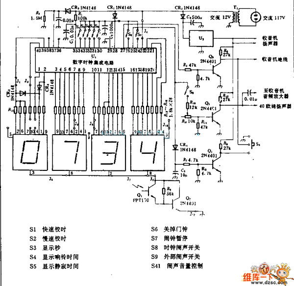
U1 is the 3817 integrated circuit, capable of directly driving the display. It can show time in either 12-hour or 24-hour format, schedule alarm sounds, and automatically turn on the radio at specified times. The display utilizes the FND500 light-emitting...
One-Shot Multivibrator
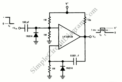
A one-shot multivibrator generates a fixed-width pulse at the output when triggered by an input signal. This fixed-width output remains consistent, regardless of the input signal duration.
The one-shot multivibrator, also known as a monostable multivibrator, is a crucial component in...
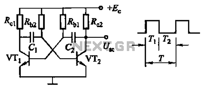
Common non-sinusoidal oscillator circuit waveform square wave oscillator self-excited multivibrator
Common non-sinusoidal oscillator circuit, waveform and frequency formula - square wave oscillator - self-excited multivibrator
The common non-sinusoidal oscillator circuit, specifically the square wave oscillator, is a fundamental electronic circuit utilized to generate square wave signals. It operates based on the...
Digital alarm clock circuit diagram
U1 is the 3817 integrated circuit, capable of directly driving the display. It can show time in either 12-hour or 24-hour format, schedule alarm sounds, and automatically turn on the radio at specified times. The display utilizes the FND500 light-emitting...

Nearly half duty cycle multlvibrator
Three factors contribute to the output symmetry. The capacitor charges and discharges through the same external resistor. An internal resistive divider sets accurate switching thresholds within the chip; the bipolar types use dividers as well. Most importantly, the CMOS output...

Multivibrator
A multivibrator is an electronic circuit that implements various simple two-state systems, such as oscillators, timers, and flip-flops. The most common type is the astable multivibrator, which continuously oscillates between two states, generating a square wave. Another type is the...
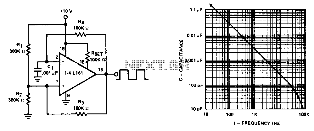
Square wave oscillator
This generator operates at frequencies exceeding 100 kHz. The lower frequency limit is determined by capacitor Cl. Additionally, the frequency remains constant for supply voltages down to +5 V.
The generator described is a versatile electronic oscillator capable of producing high-frequency...
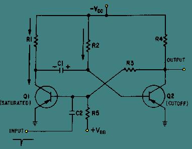
Monostable Multivibrator
The schematic for a monostable multivibrator is presented below. Similar to the astable multivibrator, one transistor conducts while the other cuts off when the circuit is powered. It is important to note that, unlike the astable multivibrator, the one-shot circuit...