


Light activated logic circuits
#light activated
#logic functions
#digital circuits
#sensors
#phototransistor
#logic gates
#electronics
#circuit design
#embedded systems
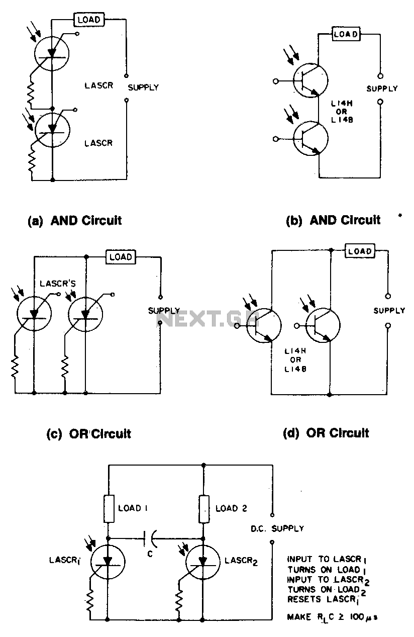
Description: These circuits illustrate some of the common logic functions that can be implemented.
The provided circuits serve as examples of fundamental logic functions utilized in digital electronics. Logic functions are the building blocks of digital systems, enabling the execution of various operations such as AND, OR, NOT, NAND, NOR, XOR, and XNOR. Each of these functions can be represented using different types of logic gates, which are the essential components of digital circuits.
1. **AND Gate**: This gate outputs a high signal (1) only if all its inputs are high. It can be represented in a schematic with two or more input lines converging at the gate, with a single output line.
2. **OR Gate**: The OR gate produces a high output if at least one of its inputs is high. Its schematic representation includes multiple input lines leading to a single output line.
3. **NOT Gate**: Also known as an inverter, this gate outputs the opposite value of its single input. The schematic shows one input line leading to the gate and one output line.
4. **NAND Gate**: This gate is a combination of an AND gate followed by a NOT gate. It outputs a low signal only when all its inputs are high. The schematic includes input lines converging at the gate, with the output line indicating the inverted result.
5. **NOR Gate**: This is the opposite of the OR gate, producing a high output only when all inputs are low. Its schematic resembles that of an OR gate but includes an inversion at the output.
6. **XOR Gate**: The exclusive OR gate outputs high when an odd number of its inputs are high. The schematic displays multiple input lines leading to a single output, indicating the exclusive condition.
7. **XNOR Gate**: This gate is the complement of the XOR gate, outputting high when an even number of inputs are high. Its schematic representation is similar to that of the XOR gate but includes an inversion at the output.
These logic functions can be combined in various configurations to create more complex circuits, such as multiplexers, demultiplexers, encoders, and decoders, which are essential in digital communication and processing systems. The understanding and implementation of these basic logic functions are crucial for designing efficient electronic circuits that perform specific tasks within a system.These circuits illustrate some of the common logic functions that can be implemented.
The provided circuits serve as examples of fundamental logic functions utilized in digital electronics. Logic functions are the building blocks of digital systems, enabling the execution of various operations such as AND, OR, NOT, NAND, NOR, XOR, and XNOR. Each of these functions can be represented using different types of logic gates, which are the essential components of digital circuits.
1. **AND Gate**: This gate outputs a high signal (1) only if all its inputs are high. It can be represented in a schematic with two or more input lines converging at the gate, with a single output line.
2. **OR Gate**: The OR gate produces a high output if at least one of its inputs is high. Its schematic representation includes multiple input lines leading to a single output line.
3. **NOT Gate**: Also known as an inverter, this gate outputs the opposite value of its single input. The schematic shows one input line leading to the gate and one output line.
4. **NAND Gate**: This gate is a combination of an AND gate followed by a NOT gate. It outputs a low signal only when all its inputs are high. The schematic includes input lines converging at the gate, with the output line indicating the inverted result.
5. **NOR Gate**: This is the opposite of the OR gate, producing a high output only when all inputs are low. Its schematic resembles that of an OR gate but includes an inversion at the output.
6. **XOR Gate**: The exclusive OR gate outputs high when an odd number of its inputs are high. The schematic displays multiple input lines leading to a single output, indicating the exclusive condition.
7. **XNOR Gate**: This gate is the complement of the XOR gate, outputting high when an even number of inputs are high. Its schematic representation is similar to that of the XOR gate but includes an inversion at the output.
These logic functions can be combined in various configurations to create more complex circuits, such as multiplexers, demultiplexers, encoders, and decoders, which are essential in digital communication and processing systems. The understanding and implementation of these basic logic functions are crucial for designing efficient electronic circuits that perform specific tasks within a system.These circuits illustrate some of the common logic functions that can be implemented.
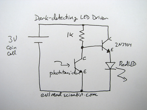
phototransistor Light sensor using Photo Transistor
A circuit that uses a phototransistor to create a light-sensitive switch. When there is no light in the room, the LED connected to the phototransistor lights up, and when there is light, the LED turns off. Any schematic or circuit...
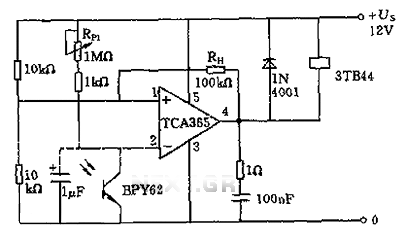
Light intensity 10 a 10LX twilight light control switch circuit diagram
A bridge input circuit utilizing a phototransistor BPY62 and a power operational amplifier is capable of controlling power loads up to 8.5 kW. It features a voltage divider composed of two 10 kΩ resistors, creating a midpoint connection. The operational...
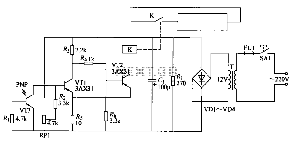
Auto Cutter mill circuit
The cutter is safeguarded by a printed circuit phototransistor designed to prevent accidental activation of the cutter switch during manual feeding. In the event of manual feeding, the automatic paper cutter can be controlled to shut down. A relay with...
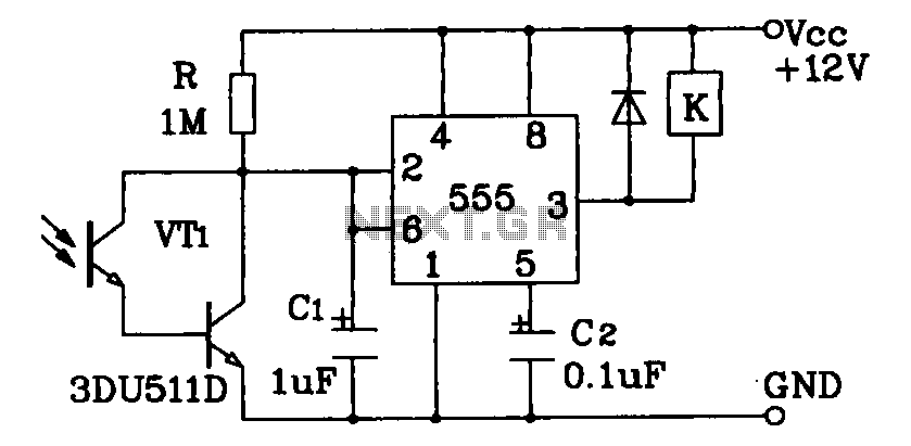
Darlington phototransistor type light control switch circuit diagram sensitive application
Darlington phototransistor type light-sensitive switch control circuit application. The Darlington type phototransistor serves as a sensitive element, capable of detecting low light levels for the detection of reflected light signals.
The Darlington phototransistor circuit utilizes a pair of transistors configured to...
Electronic Projects
This program includes circuit design CAD, simulation, and auto-routing PC layout. PSPICE is also utilized at Unisys, which offers more capabilities but costs six times as much and requires annual renewal. With these requirements and others in mind, a variation...
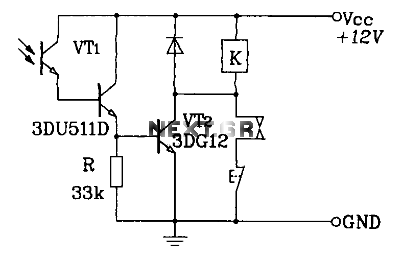
Photoelectric control relay circuit Darlington type phototransistor with self-locking function
A Darlington phototransistor serves as the primary component for the photoelectric function within a self-locking control relay circuit.
The circuit utilizes a Darlington phototransistor, which is known for its high current gain and sensitivity to light. This device is configured to...
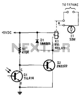
Simple Photoelectric Light Controller
A phototransistor detects daylight. At dusk, it stops conducting, and Rl biases Q2, activating Kl, which turns on the light. At dawn, Ql begins to conduct, cutting off Q2. Kl deactivates, and the light turns off.
The circuit utilizes a phototransistor...
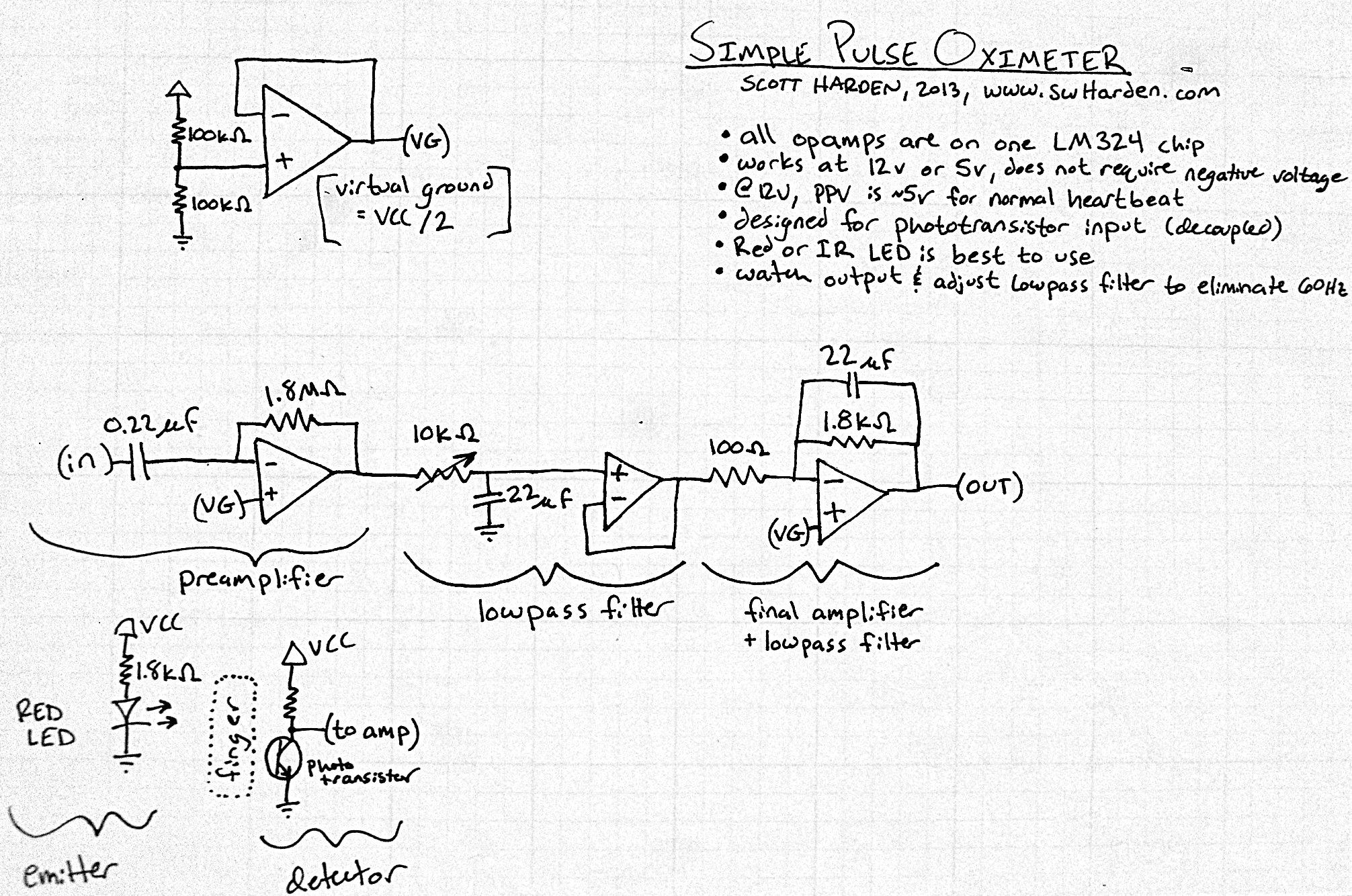
Pulse meter circuit
The input capacitor for the phototransistor at the bottom is responsible for feeding the operational amplifier (op-amp). However, the output from the phototransistor consistently remains between ground (GND) and the supply voltage (Vcc). The necessity for an input capacitor arises...
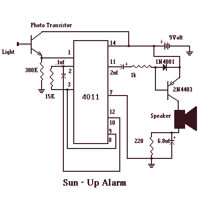
Sun - Up Alarm with 4011
The Sun - Up Alarm can be used to provide an audible alarm for when the sun comes up or it can be used in a dark area and detect when a light comes on. It can also be used...