


Noisy-signals-filter
#noise filter
#digital signals
#contact bounce
#glitch removal
#counter
#flip-flop
#signal conditioning
#debounce
#frequency adjustment
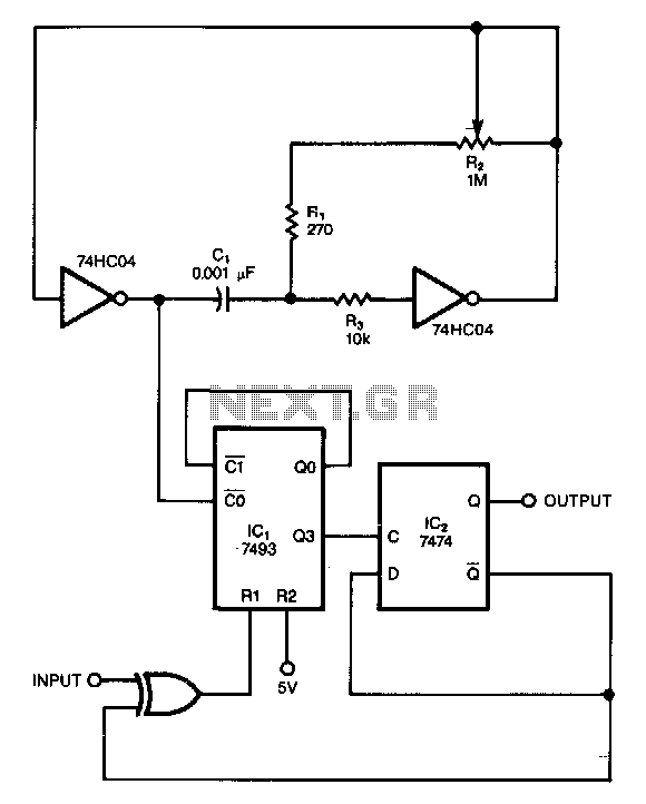
Description: This circuit filters noise, such as glitches and contact bounce, from digital signals. It can be easily adjusted for a wide range of noise frequencies. The circuit's output changes state only if the input differs from the output long enough for the counter to count eight cycles. If the input changes before the counter reaches its maximum count, the counter resets without clocking the output of flip-flop IC2. The resistor R2 is used to set the frequency of the two-inverter CMOS oscillator, which clocks the counter. The oscillator should be adjusted so that its period is one-eighth that of the noise intended for elimination.
This circuit serves as an effective noise filter for digital signals, particularly in applications where contact bounce and transient glitches can lead to erroneous signal interpretation. The primary function is to ensure that the output state of the circuit remains stable unless the input signal remains consistent over a specified duration, allowing for reliable signal processing.
The core of the circuit includes a counter that monitors the input signal. This counter must count to eight cycles before any change in the output state occurs. This design choice introduces a debounce mechanism, effectively filtering out brief fluctuations in the input signal that do not represent legitimate state changes. If the input signal returns to its original state before the counter completes its count, the counter resets, preventing any unintended state changes in the output.
The oscillator, built using two CMOS inverters, generates a clock signal that drives the counter. The frequency of this oscillator is crucial, as it determines the responsiveness of the system. By adjusting the resistor R2, the frequency can be tuned to achieve an oscillator period that is one-eighth of the targeted noise frequency. This ensures that the circuit is optimally configured to filter out specific noise characteristics while maintaining the integrity of the desired digital signals.
Overall, this circuit is a valuable tool for enhancing the reliability of digital systems by mitigating the effects of noise and ensuring that only valid signals are processed.This circuit filters noise, such as glitches and contact bounce, from digital signals. You can easily adjust the circuit for a wide range of noise frequencies. The circuit"s output changes state only if the input differs from the output long enough for the counter to count eight cycles. If the input changes before the counter reaches its maximum count, the counter resets without clocking the output of flipflop, IC2.
You use R2 to set the frequency of the two-inverter CMOS oscillator, which clocks the counter. Simply adjust the oscillator such that its period is one-eighth that of the noise you want to eliminate.
This circuit serves as an effective noise filter for digital signals, particularly in applications where contact bounce and transient glitches can lead to erroneous signal interpretation. The primary function is to ensure that the output state of the circuit remains stable unless the input signal remains consistent over a specified duration, allowing for reliable signal processing.
The core of the circuit includes a counter that monitors the input signal. This counter must count to eight cycles before any change in the output state occurs. This design choice introduces a debounce mechanism, effectively filtering out brief fluctuations in the input signal that do not represent legitimate state changes. If the input signal returns to its original state before the counter completes its count, the counter resets, preventing any unintended state changes in the output.
The oscillator, built using two CMOS inverters, generates a clock signal that drives the counter. The frequency of this oscillator is crucial, as it determines the responsiveness of the system. By adjusting the resistor R2, the frequency can be tuned to achieve an oscillator period that is one-eighth of the targeted noise frequency. This ensures that the circuit is optimally configured to filter out specific noise characteristics while maintaining the integrity of the desired digital signals.
Overall, this circuit is a valuable tool for enhancing the reliability of digital systems by mitigating the effects of noise and ensuring that only valid signals are processed.This circuit filters noise, such as glitches and contact bounce, from digital signals. You can easily adjust the circuit for a wide range of noise frequencies. The circuit"s output changes state only if the input differs from the output long enough for the counter to count eight cycles. If the input changes before the counter reaches its maximum count, the counter resets without clocking the output of flipflop, IC2.
You use R2 to set the frequency of the two-inverter CMOS oscillator, which clocks the counter. Simply adjust the oscillator such that its period is one-eighth that of the noise you want to eliminate.
Counter
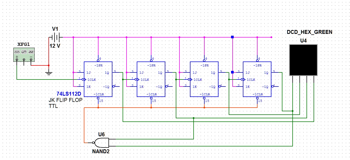
This article discusses the term "counter" as it relates to electronics and computing. For additional meanings, refer to the term "Counter" in disambiguation. In digital logic and computing, a counter is a device that stores (and occasionally displays) the number...
digital switching system
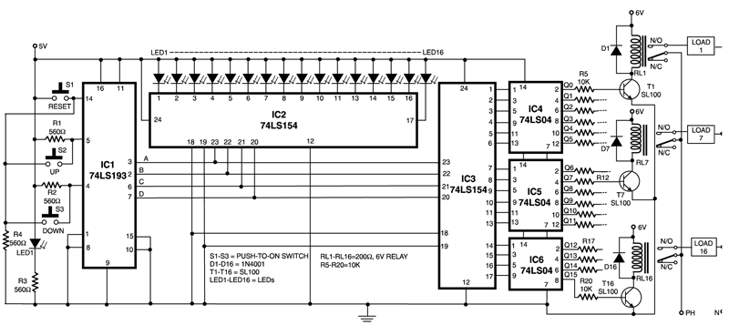
This circuit is capable of controlling one out of 16 devices using two push-to-on switches. An up/down counter functions as the master controller for the system, and visual feedback is provided through LEDs. The circuit employs IC1 (74LS193), which is...
Signal Conditioners Information
Signal conditioning involves a series of operations applied to a signal to make it compatible for interfacing with other devices or systems. Signal conditioners are the devices that execute this operation, featuring both an input and an output. Typically, the...
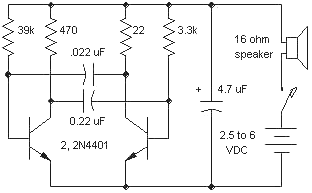
Astable Flip-flops
The astable flip-flop circuit is a versatile configuration used for creating flashers or generating square waves. A common application is an alternating LED flasher where the LEDs are connected in the emitters instead of the collectors, which is the more...
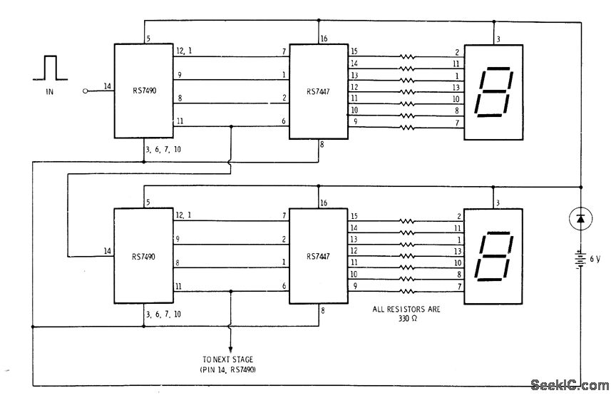
MULTIDIGIT DEMONSTRATION COUNTER
A simple interconnection of the RS7490 decade counter, RS7447 decoder, and a 7-segment digital display for each desired digit creates an ideal counter for classroom demonstrations and science fair exhibits. With the addition of two extra stages, the display can...
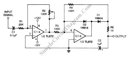
Averager and Peak Hold/Extender Signal Conditioner
A signal averager circuit can be formed by an amplifier and active signal rectifier, which is implemented using two operational amplifiers in this circuit.
The signal averager circuit utilizes two operational amplifiers (op-amps) to achieve signal averaging through amplification and rectification....
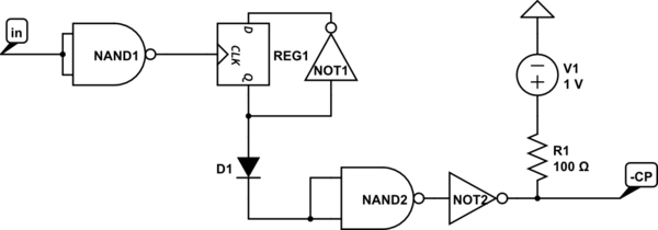
flipflop Purpose of the logic gate configurations on the Kenbak-1
This text discusses the functionality of a flip-flop, specifically focusing on the role of two NAND gates and the presence of an additional inverter. It suggests allowing time for others to analyze the question and formulate their theories, emphasizing that...
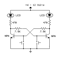
Set reset flip-flop circuit
This is an example of a set/reset flip flop using discrete components. When power is applied, only one of the transistors will conduct causing the other to remain off. More: The conducting transistor can be turned off by grounding its...
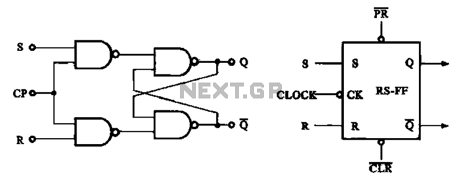
Synchronous RS flip-flop circuit structure and symbols
The asynchronous RS flip-flop mentioned earlier is not synchronized with the system clock signal. In contrast, the synchronous RS flip-flop incorporates synchronization, allowing it to operate in conjunction with the clock signal. Figure (a) illustrates the circuit configuration of the...