


Optocouplers and transistors of the bistable circuit diagram
#optocoupler
#transistor
#bistable
#circuit
#switching
#logic
#electronics
#signal
#voltage
#control
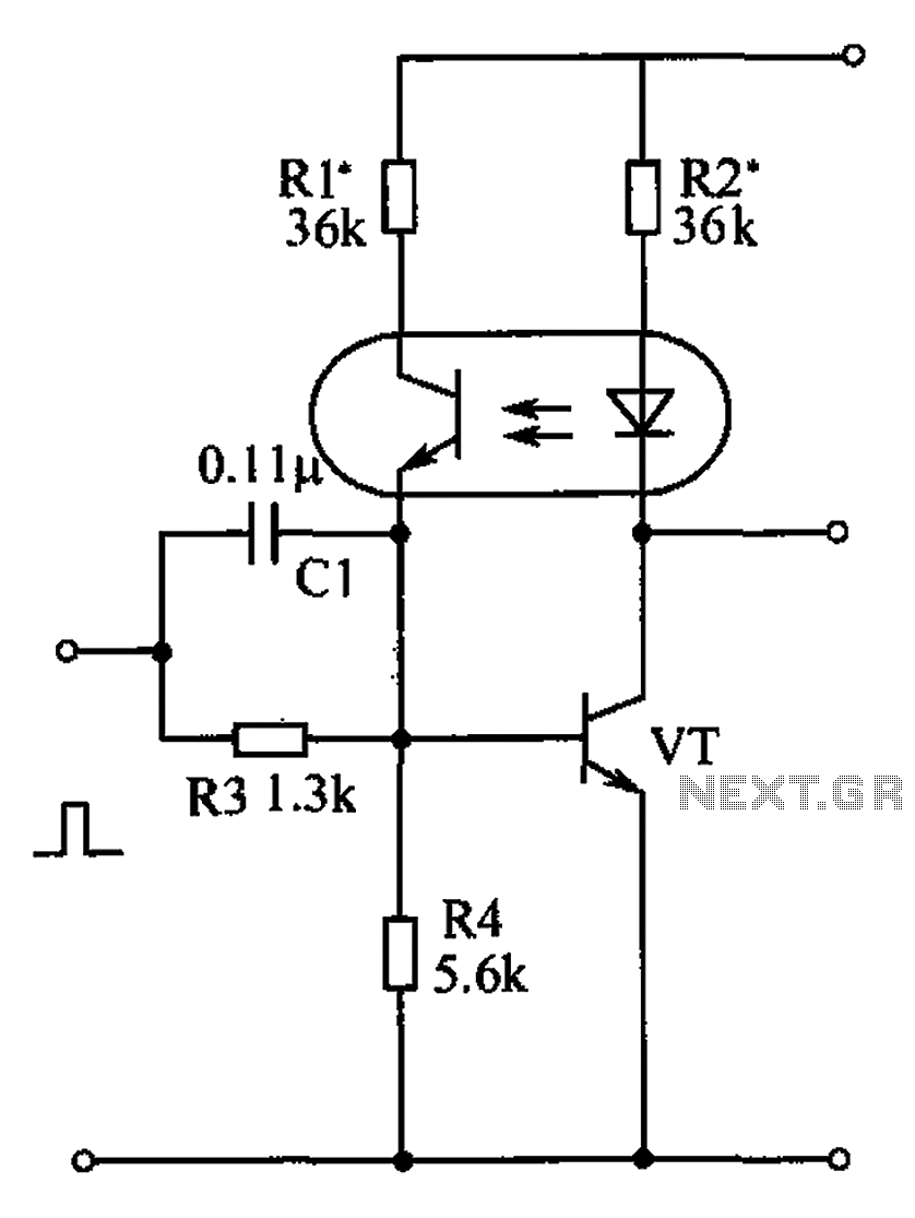
Description: The bistable circuit and optocoupler transistor operate as illustrated in the accompanying figure. Initially, when the supply voltage is applied, the transistor VT is in the off state, resulting in a high output potential. Upon receiving a forward pulse at the input terminal, the collector current of VT increases, which activates the light-emitting diode (LED) of the optocoupler. This action reduces the collector-emitter resistance of the phototransistor, leading to an increase in the base current of VT. This creates positive feedback, quickly driving VT into saturation, causing a transition from a high (1) to a low (0) output. Conversely, when a negative pulse is introduced, the collector current of VT decreases, which dims the LED and reduces the base current of VT. This further decreases the collector current, resulting in a rapid turn-off of VT, causing the LED to extinguish and the phototransistor to deactivate, stabilizing VT in the off state and transitioning the flip-flop from a low (0) to a high (1) state. This configuration enhances the noise immunity of the bistable circuit.
The bistable circuit described operates based on the principles of feedback and optical isolation provided by the optocoupler. The circuit employs a transistor (VT) that serves as a switching element, which can toggle between two states: on and off. The initial state of the circuit is defined when the supply voltage is applied, at which point VT is off, resulting in a high output potential.
When a forward pulse signal is applied to the input terminal, it triggers an increase in the collector current of VT. This increase activates the optocoupler's light-emitting diode, which emits light that is detected by the phototransistor. The phototransistor's response reduces its collector-emitter resistance, allowing more base current to flow into VT. This feedback loop amplifies the base current, driving VT into saturation rapidly, which flips the output from high to low.
In the case of a negative pulse, the process reverses. The decrease in collector current causes the LED of the optocoupler to dim, which in turn reduces the base current of VT. The reduction in base current further decreases the collector current, leading to a swift turn-off of VT. As a result, the LED turns off, the phototransistor becomes inactive, and VT stabilizes in the off state, shifting the flip-flop back to a high output state.
This bistable configuration is particularly advantageous due to its resilience to noise, making it suitable for applications where signal integrity is critical. The use of an optocoupler provides electrical isolation between the input and output, enhancing the circuit's robustness against external disturbances. Overall, the design effectively leverages feedback mechanisms and optical components to create a reliable bistable switching circuit. As shown by the bistable circuit and optocoupler transistor of FIG. In the initial state the moment the supply voltage is turned on, the transistor VT off, the circuit outputs a high potential. When the input terminal with a forward pulse, so that the collector current increases VT, optocoupler light emitting diode, phototransistor collector-emitter resistance among smaller, resulting in VT base current increases, the formation of positive feedback, so fast VT saturation, from 1 to 0. When you enter a negative pulse, VT collector current decreases, thereby enabling VT darken the light emitting diode base current decreases, causing VT collector current is further reduced, so that VT quickly turned off, and the light emitting diode does not light, phototransistor is turned off, so that VT stable in the off state, the flip-flop from 0 to l state.
This can improve the anti-jamming capability bistable circuit bistable circuit.
The bistable circuit described operates based on the principles of feedback and optical isolation provided by the optocoupler. The circuit employs a transistor (VT) that serves as a switching element, which can toggle between two states: on and off. The initial state of the circuit is defined when the supply voltage is applied, at which point VT is off, resulting in a high output potential.
When a forward pulse signal is applied to the input terminal, it triggers an increase in the collector current of VT. This increase activates the optocoupler's light-emitting diode, which emits light that is detected by the phototransistor. The phototransistor's response reduces its collector-emitter resistance, allowing more base current to flow into VT. This feedback loop amplifies the base current, driving VT into saturation rapidly, which flips the output from high to low.
In the case of a negative pulse, the process reverses. The decrease in collector current causes the LED of the optocoupler to dim, which in turn reduces the base current of VT. The reduction in base current further decreases the collector current, leading to a swift turn-off of VT. As a result, the LED turns off, the phototransistor becomes inactive, and VT stabilizes in the off state, shifting the flip-flop back to a high output state.
This bistable configuration is particularly advantageous due to its resilience to noise, making it suitable for applications where signal integrity is critical. The use of an optocoupler provides electrical isolation between the input and output, enhancing the circuit's robustness against external disturbances. Overall, the design effectively leverages feedback mechanisms and optical components to create a reliable bistable switching circuit. As shown by the bistable circuit and optocoupler transistor of FIG. In the initial state the moment the supply voltage is turned on, the transistor VT off, the circuit outputs a high potential. When the input terminal with a forward pulse, so that the collector current increases VT, optocoupler light emitting diode, phototransistor collector-emitter resistance among smaller, resulting in VT base current increases, the formation of positive feedback, so fast VT saturation, from 1 to 0. When you enter a negative pulse, VT collector current decreases, thereby enabling VT darken the light emitting diode base current decreases, causing VT collector current is further reduced, so that VT quickly turned off, and the light emitting diode does not light, phototransistor is turned off, so that VT stable in the off state, the flip-flop from 0 to l state.
This can improve the anti-jamming capability bistable circuit bistable circuit.
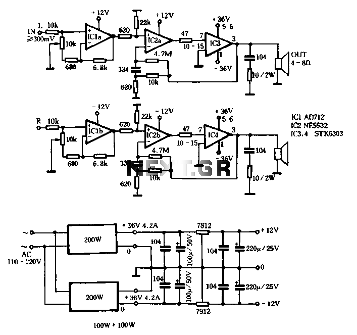
Switching power supply circuit with STK6303
The T amplifier circuit schematic section is illustrated in Figure 3-51. It utilizes the Japan Sanyo STK6303 Pina, which is a high-power thick film integrated circuit. The maximum power supply voltage is 36V, and the output current can reach approximately...
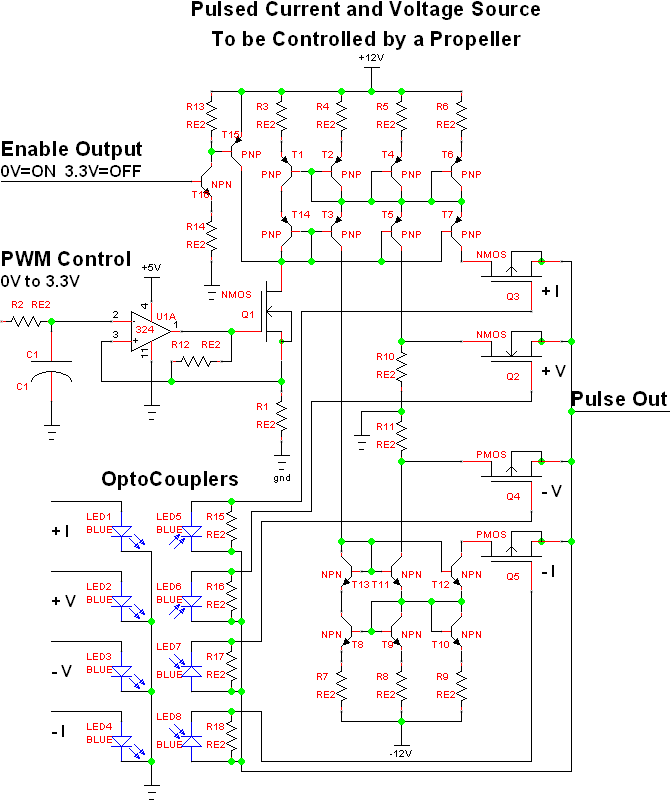
Full on transistor/fet curve tracer
The project involves adapting a curve tracer schematic, likely based on Metzger's circuit from the early 1970s, to integrate an ADC capture system and output the data to a 320x256 ELD panel. Additionally, a serial output will be included to...
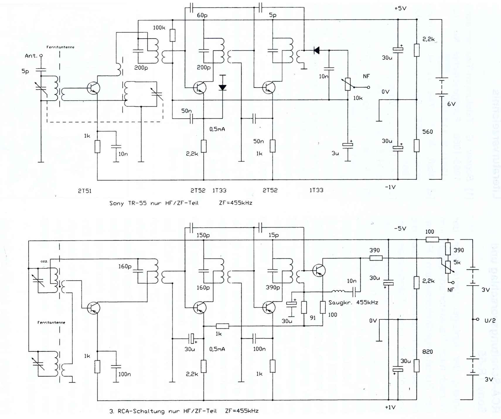
Comments on the Circuits of the first Transistor Radios
The circuitry of the Regency exhibits several unique characteristics. Notable features include the self-oscillating mixer stage, the base bias voltage of the second IF stage derived from the AF power stage, an unusual IF frequency of 262 kHz, and a...
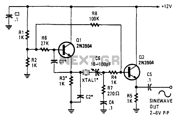
Two-Transistor Sine-Wave Oscillator
This oscillator employs two transistors and operates the crystal in its fundamental mode. Capacitors CT and C2 should be approximately 2,700 pF for 1 MHz, 680 pF for 5 MHz, and 330 pF for 10 MHz. A capacitance of 150...
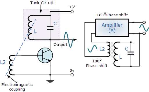
transistors LC circuit
Build the LC oscillator shown at the bottom of this page for a school project, but there are some challenges in translating the theoretical circuit into a real-world application. The understanding of the circuit's operation on paper is clear. It...
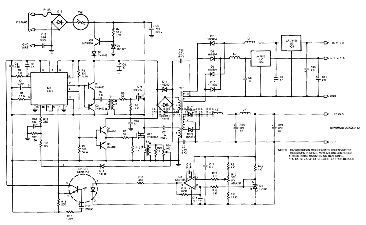
100Khz-multiple-output-switching-power-supply
The power supply employs two VN4000A 400-V MOSPOWER FETs configured in a half-bridge arrangement. It provides outputs of +5 V at 20 A and ±15 V (or ±12 V) at 1 A. The low-current outputs utilize linear three-terminal regulators, allowing...
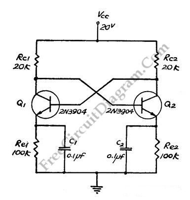
Direct Coupled Discrete Astable Multivibrator circuit
This flip-flop circuit functions as a free-running astable multivibrator, where the bases and collectors of both emitter-biased transistors are directly coupled. The switching action is facilitated by a capacitor in each emitter circuit, resulting in the generation of triangle waves...
300B solid state
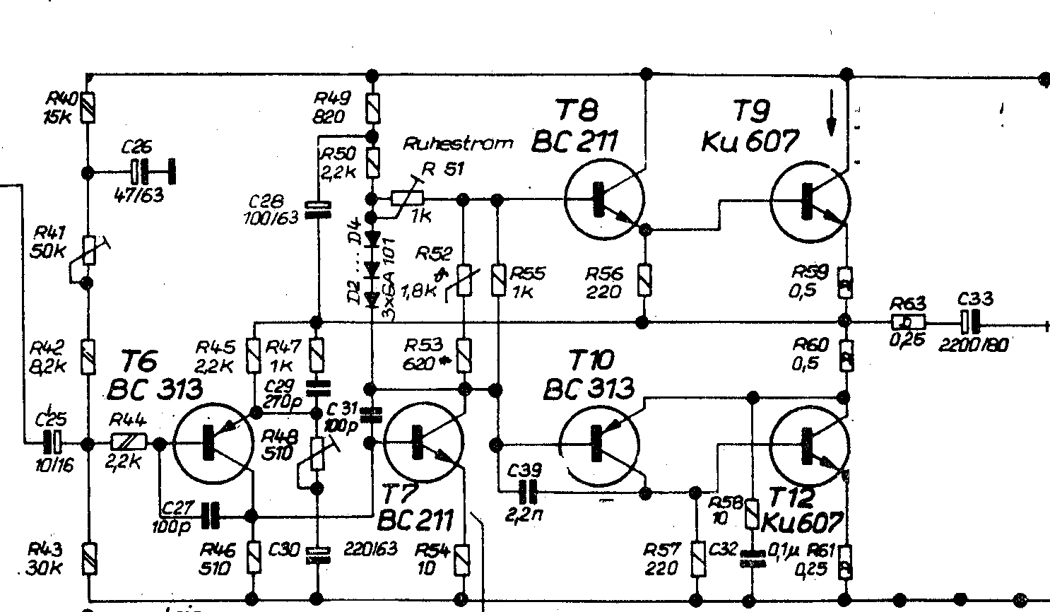
The classic 6-transistor circuit, prevalent in the 1960s and 70s, utilizes NPN output devices and features a relatively high bias level. It operates on a single rail, with input and output coupled through electrolytic capacitors. The design incorporates a clever...
Transistor Circuits
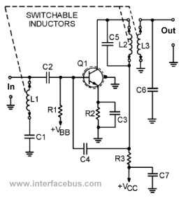
This page presents several transistor circuits that are not commonly found on other pages due to the absence of a specific topic. These circuits, however, illustrate particular points but lack detailed descriptions. An example of an RF amplifier circuit using...