


Seven-segment LED display circuit diagram of a counter
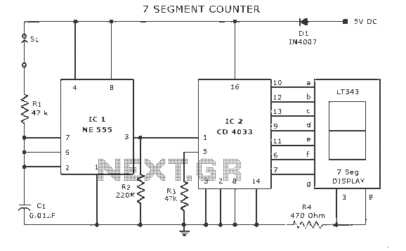
Description: A display counter circuit is illustrated through a diagram featuring a seven-segment display controlled by the counter IC CD4033. This counter circuit is designed to visually represent incremental counts, enhancing its appeal for integration into various applications. An astable multivibrator using the IC 555 is connected to the CD4033. For each trigger pulse received, the CD4033 increments the count. The current count is displayed on a seven-segment LED display. A diode (LT543) is utilized in the circuit, along with switch S1, which serves to prevent accidental activation and mitigate risks associated with polarity inversion. A parts list and circuit diagram are provided. Additional circuits of interest include a static display for numbers 0-9, an up/down counter circuit, a digital timer circuit, a long-duration timer circuit, and a scoring circuit.
The display counter circuit employs the CD4033 integrated circuit, which is specifically designed for driving seven-segment displays. The IC counts up on each pulse received at its input pin, effectively converting the pulse frequency into a visual representation through the connected seven-segment display. The astable multivibrator circuit, constructed from the 555 timer IC, generates a continuous square wave signal that acts as the trigger for the CD4033. The frequency of this signal can be adjusted by modifying the resistor and capacitor values in the 555 timer configuration, allowing for control over the counting speed.
The seven-segment display consists of individual LEDs arranged to form digits from 0 to 9. Each segment of the display is activated by specific outputs from the CD4033, which correspond to the current count. The LT543 diode ensures that current flows in the correct direction, protecting the circuit from reverse polarity conditions that could potentially damage the components. The inclusion of switch S1 provides an additional layer of safety by allowing the user to disable the circuit when not in use, thereby preventing unintended counting or circuit activation.
This display counter circuit can be adapted for various applications, including educational demonstrations, digital timers, and scoring systems. The flexibility of the CD4033 and the astable multivibrator configuration makes it suitable for creating a range of counting and timing devices. The provided parts list and circuit diagrams facilitate easy replication and experimentation, enabling users to explore additional functionalities or modifications to enhance the circuit's performance.Display counter circuit Explanation Here is a circuit diagram of a seven-segment on the counter IC CD 4033. This counter circuit in which a counter to show the progress increased attractiveness for use with some of the various circuits. Astable multivibrator IC 555 wired northeast CD 4033.For each trigger pulse, CD 4033 CD 4033 count.The progress output seven segment LED display shows counting.Diode LT543.Switch S1 is used to prevent accidental starting of D1 polarity inversion risk.
Seven parts list and circuit diagrams. Some circuits, you might want to see. Displaying 1, the static 0-9 2, up / down counter circuit 3, a digital timer circuit 4, long duration timer circuit 5, scoring circuit.
The display counter circuit employs the CD4033 integrated circuit, which is specifically designed for driving seven-segment displays. The IC counts up on each pulse received at its input pin, effectively converting the pulse frequency into a visual representation through the connected seven-segment display. The astable multivibrator circuit, constructed from the 555 timer IC, generates a continuous square wave signal that acts as the trigger for the CD4033. The frequency of this signal can be adjusted by modifying the resistor and capacitor values in the 555 timer configuration, allowing for control over the counting speed.
The seven-segment display consists of individual LEDs arranged to form digits from 0 to 9. Each segment of the display is activated by specific outputs from the CD4033, which correspond to the current count. The LT543 diode ensures that current flows in the correct direction, protecting the circuit from reverse polarity conditions that could potentially damage the components. The inclusion of switch S1 provides an additional layer of safety by allowing the user to disable the circuit when not in use, thereby preventing unintended counting or circuit activation.
This display counter circuit can be adapted for various applications, including educational demonstrations, digital timers, and scoring systems. The flexibility of the CD4033 and the astable multivibrator configuration makes it suitable for creating a range of counting and timing devices. The provided parts list and circuit diagrams facilitate easy replication and experimentation, enabling users to explore additional functionalities or modifications to enhance the circuit's performance.Display counter circuit Explanation Here is a circuit diagram of a seven-segment on the counter IC CD 4033. This counter circuit in which a counter to show the progress increased attractiveness for use with some of the various circuits. Astable multivibrator IC 555 wired northeast CD 4033.For each trigger pulse, CD 4033 CD 4033 count.The progress output seven segment LED display shows counting.Diode LT543.Switch S1 is used to prevent accidental starting of D1 polarity inversion risk.
Seven parts list and circuit diagrams. Some circuits, you might want to see. Displaying 1, the static 0-9 2, up / down counter circuit 3, a digital timer circuit 4, long duration timer circuit 5, scoring circuit.
Homemade Digital CALL-ID English Version
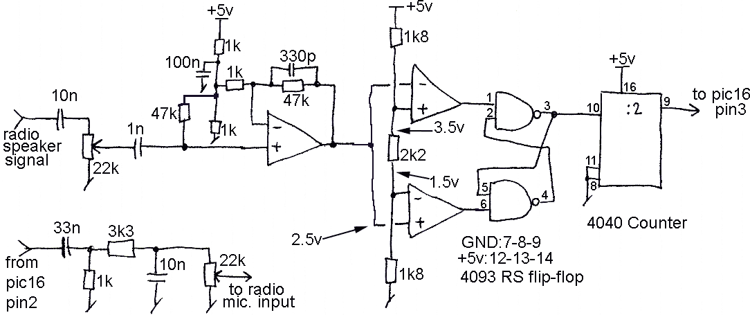
The reason for this project was to facilitate a quick installation for a local friend 10 km away, enabling the start of real-life testing to identify and resolve bugs and problems before releasing it to other users. The software is...
High Precision Digital Pulse Meter Circuit
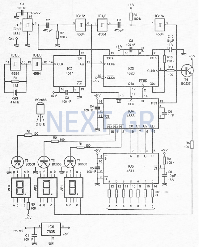
This compact device, designed primarily for modelers, provides instantaneous readings of pulse duration in milliseconds (ms). It can measure servomotor positions, typically ranging from 1 ms to 2 ms, and can also perform repetitive or non-pulsed measurements, such as the...
Woodstock HP-21 HP-25
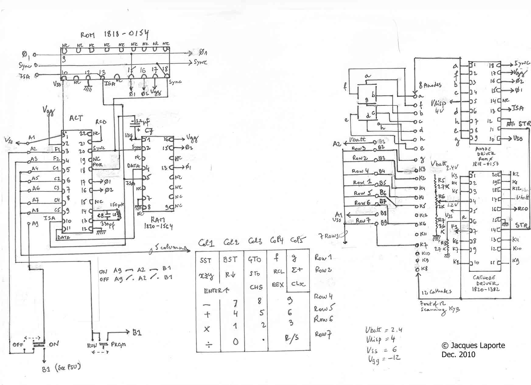
The machine utilizes a 12-digit display consisting of 8 LED anodes controlled by an anode driver, and 12 digits managed by a cathode driver, which also scans the keyboard's 7 columns. The bus is simplified to 4 lines: two clock...
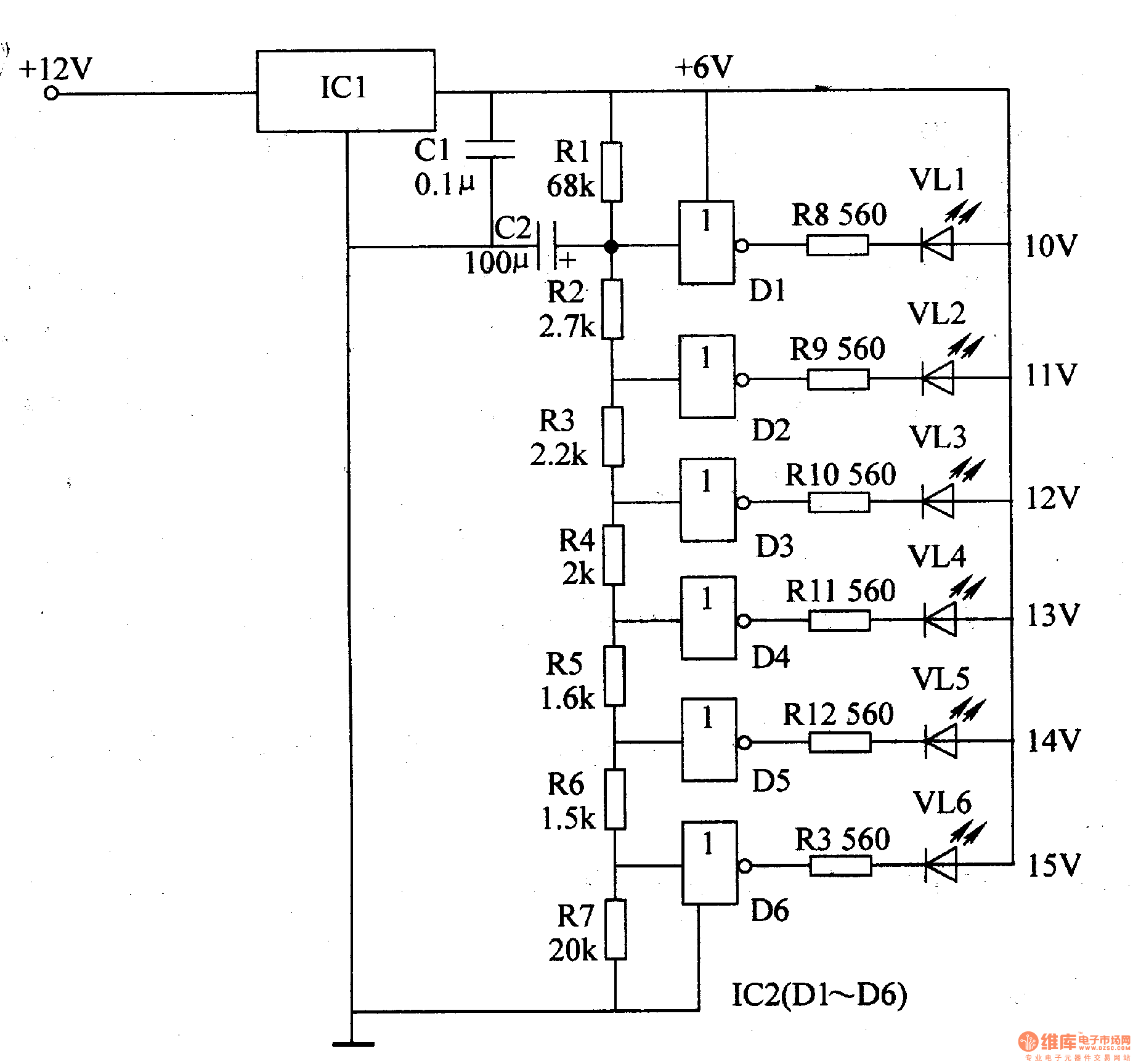
The LED car voltmeter (3)
The LED car voltmeter comprises a filter circuit, a voltage distribution filter circuit, a voltage amplifier circuit, and an LED display circuit, as illustrated in Figure 7-77. The regulator filter circuit includes a 3-terminal IC (IC1) and a filter capacitor...
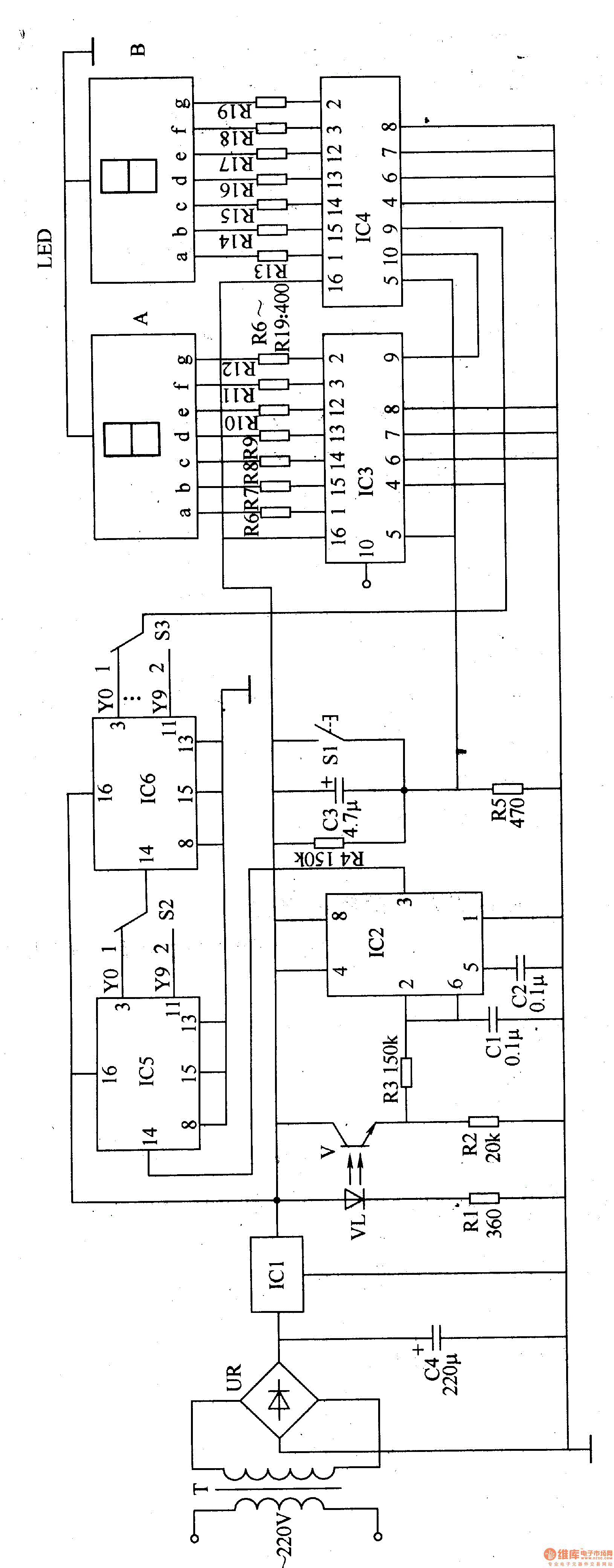
Winding electronic counter 2
The electronic counter of the winding machine utilizes an LED digital display to indicate the number of turns of the wound coil, with a maximum counting capacity of 9900 turns. The operational principle of the winding machine circuit consists of...
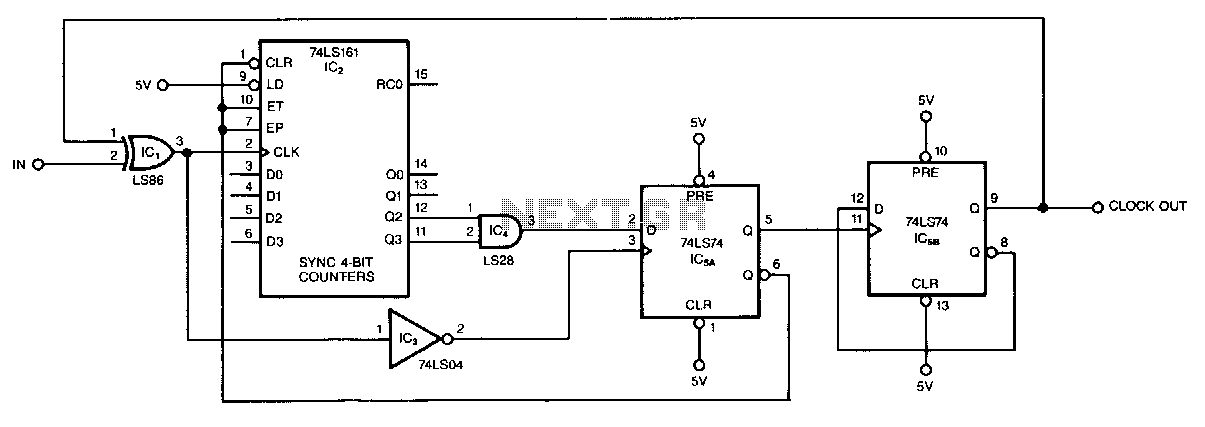
Odd-number-counter-divider
This circuit, illustrated symmetrically, divides an input by virtually any odd number. The circuit counts n + 1/2 clocks twice to achieve the desired divisor. By selecting the appropriate n, which is the decoded output of the LS161 counter, divisors...
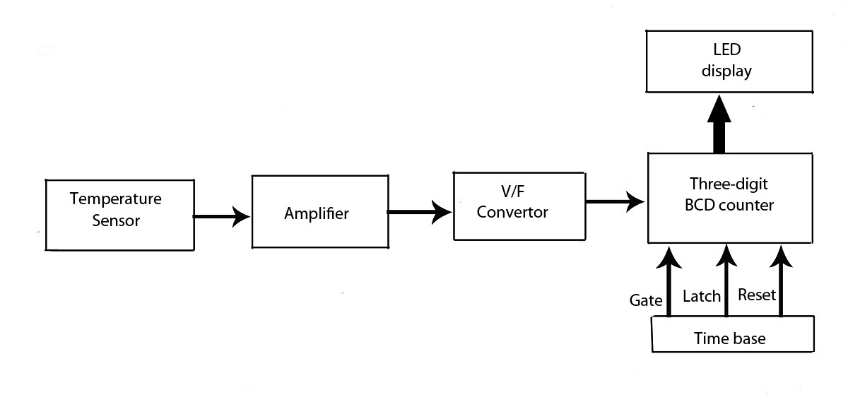
Advanced LED Temperature Indicator
This verified project provides an idea, circuit, and operation of the LED display temperature indicator. It features a digital temperature indicator utilizing a voltage-to-frequency (V/F) converter, along with various electronic projects.
The LED display temperature indicator is designed to provide a...
Ring Counter Circuit Working Principle with Animation and Video
Digital counters have various applications in electronic circuits. In digital electronics, counters are utilized in different situations. This article presents the concept of a ring counter circuit, which functions as a register counter. An animation and simulation video of the...
.gif "Audio Level Meter VU Meter circuit")
Audio Level Meter (VU Meter)
This circuit utilizes a single integrated circuit (IC) along with a minimal number of external components to display audio levels through ten LEDs. The input voltage range is from 12V to 20V, with a recommendation for 12V. The LM3915 is...