


TICK TACK TOE LOGIC
#neon lamps
#diode gates
#thyratron
#relays
#game logic
#memory circuit
#referee sequence
#tick tack toe
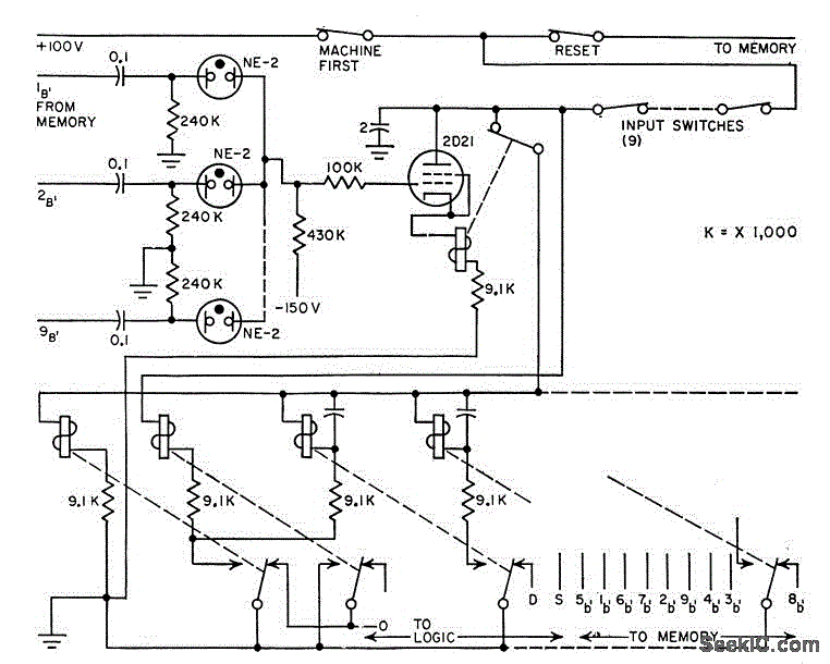
Description: Neon lamps function as diode gates and indicate positions and moves on a game board. The thyratron-relay combination acts as memory, while relays manage the sequence to prevent two successive moves by either player.
Neon lamps are utilized in this circuit as visual indicators, representing the state of each position on the game board. When a player makes a move, the corresponding neon lamp illuminates, providing a clear visual cue of the current game state. The use of thyratrons in conjunction with relays forms a robust memory element that retains the game state and ensures that the sequence of moves adheres to the rules of the game.
The thyratron functions as a switching device that can handle high voltages and currents, making it suitable for this application. It is triggered by the input from the game board, allowing the circuit to remember the last move made by a player. The relay system further enhances this by controlling the flow of current to the neon lamps, ensuring that no player can make two consecutive moves. This is achieved through a carefully designed timing mechanism within the relay system, which enforces the turn-taking rules of the game.
The integration of these components creates a reliable and efficient electronic game board that not only provides an engaging user experience but also demonstrates fundamental principles of electronic logic and memory storage. The design exemplifies the application of basic electronic components in a practical scenario, showcasing their functionality in a game setting.Neon lamps serve as diode gates and indicate positions and moves on game board. Thyratron-relay com bination serves as memory, while relays referee sequence to prevent two successive moves by either player. -C. E. Hendrix and R. B. Purcell, Neon Lamp Logic Gates Play Tick-Tack-Toe, Electronics, 31:25, p 68-69.
Neon lamps are utilized in this circuit as visual indicators, representing the state of each position on the game board. When a player makes a move, the corresponding neon lamp illuminates, providing a clear visual cue of the current game state. The use of thyratrons in conjunction with relays forms a robust memory element that retains the game state and ensures that the sequence of moves adheres to the rules of the game.
The thyratron functions as a switching device that can handle high voltages and currents, making it suitable for this application. It is triggered by the input from the game board, allowing the circuit to remember the last move made by a player. The relay system further enhances this by controlling the flow of current to the neon lamps, ensuring that no player can make two consecutive moves. This is achieved through a carefully designed timing mechanism within the relay system, which enforces the turn-taking rules of the game.
The integration of these components creates a reliable and efficient electronic game board that not only provides an engaging user experience but also demonstrates fundamental principles of electronic logic and memory storage. The design exemplifies the application of basic electronic components in a practical scenario, showcasing their functionality in a game setting.Neon lamps serve as diode gates and indicate positions and moves on game board. Thyratron-relay com bination serves as memory, while relays referee sequence to prevent two successive moves by either player. -C. E. Hendrix and R. B. Purcell, Neon Lamp Logic Gates Play Tick-Tack-Toe, Electronics, 31:25, p 68-69.
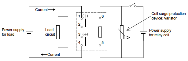
high capacity dc power relays
The value may vary based on the switching frequency, environmental conditions, and required reliability level; therefore, it is advisable to verify this with the actual load. The maximum ambient temperature represents the highest temperature that can meet the coil temperature...
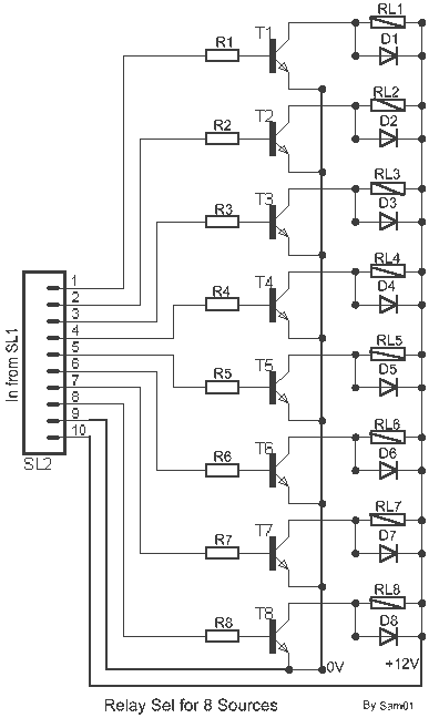
8 input Relays circuit
It is the essential continuity of circuits Sel 8 Sources and Up/Down Sel 8 Sources, but can work and autonomously, collaborating with any suitable circuit of control. The Relay 1-8 can be 6-24v DC. For current of collector of transistors...
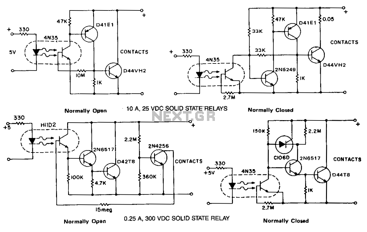
Normally-open-and-closed-relays
The phototransistor and photodarlington couplers function as direct current relays in saturated switching, handling currents up to 5 mA and 50 mA, respectively. For applications requiring higher currents or voltage capabilities, supplementary devices are necessary to buffer or amplify the...
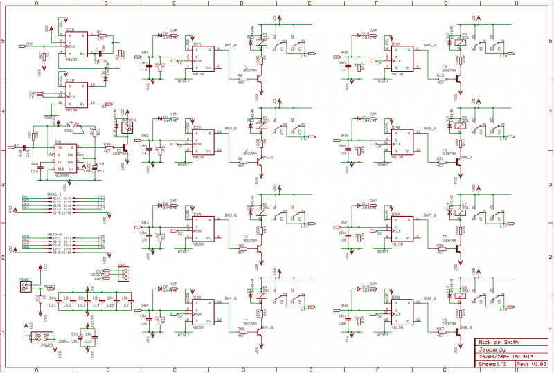
Fastest Finger First project
If 12V relays are used, you can replace the 180R resistors R7, R9, R14, R16, R20, R22, R26, and R28 with a wire link (the resistors are only there to limit current if you use 5V relays, of which I...
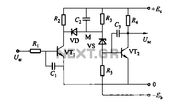
Discharge After the memory circuit
The discharge process in the memory circuit is an instantaneous action, followed by a delay reset circuit. When the input signal is activated, the circuit opens. Once the input signal is removed, the circuit begins counting after a predetermined time,...
Fastest Finger First project
If 12V relays are used, you can replace the 180R resistors R7, R9, R14, R16, R20, R22, R26, and R28 with a wire link (the resistors are only there to limit current if you use 5V relays, of which I...
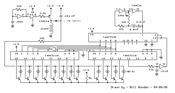
12 Stage Neon Sequencer (NE-2 / NE-51) circuit
This circuit resembles an LED clock but utilizes 12 neon indicator lamps in place of LEDs. It operates on two high-capacity nickel-cadmium cells (2.5 volts), providing power for several weeks. A small switching power supply generates the high voltage (70...

original electric furnace
This is a switched system, which does not utilize a sequencer like modern electric furnaces. Instead, it employs relays. An upgrade to install a sequencer may be beneficial. The system features a 5-speed blower, although only two speeds appear to...
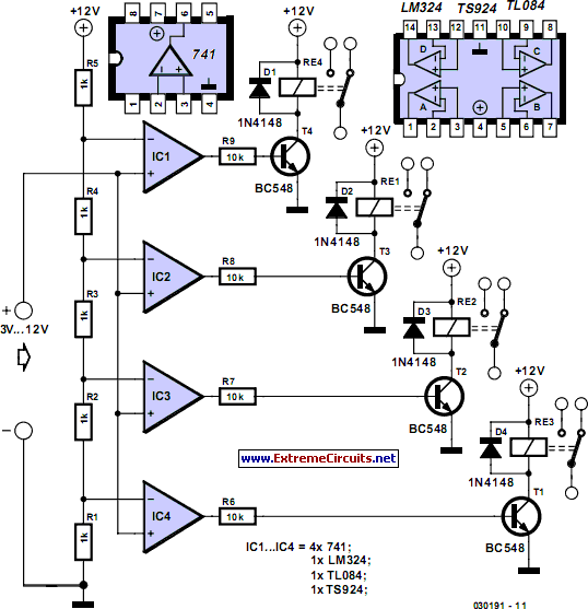
Voltage Levels Control Relays
This circuit demonstrates that microprocessors, PCs, and modern ultra-accurate Digital-to-Analog Converters (DACs) are excessive for controlling four relays in sequence based on a control voltage ranging from 2.4 V to 12 V. By utilizing equal resistors in a ladder network...