


Using C-MOS IC count divider circuit
#C-MOS
#counter
#frequency divider
#TC4040
#digital circuit
#pulse signal
#logic IC
#12-bit
#14-bit
#signal processing
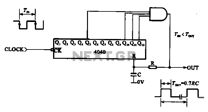
Description: This document illustrates the application of a CMOS integrated circuit (IC) count divider, specifically the TC4040, which functions as a 12- or 14-bit counter. The circuit can be configured to achieve various frequency division ratios, such as a 1:3600 divider, allowing for the transformation of a one-second signal period into a pulse signal that represents one hour.
The TC4040 is a versatile CMOS binary counter that can be employed in a variety of applications, including timekeeping, frequency division, and digital signal processing. The device operates by counting the number of input pulses and providing a corresponding binary output. It features a cascading architecture, allowing multiple TC4040 chips to be connected in series to extend the counting range beyond 12 or 14 bits.
In practical applications, the TC4040 can be configured to divide an input frequency by a specified ratio. For instance, in a 1:3600 divider configuration, the circuit takes an input clock signal (such as a 1 Hz signal) and produces an output pulse every hour. This is particularly useful in applications where long-duration timing is required, such as in digital clocks or timers.
The circuit typically consists of the TC4040 IC, a power supply, and input/output connections. The IC requires a stable DC power supply, usually between 3V to 15V, depending on the specific model and application requirements. Input signals are fed into the clock pin of the TC4040, while the output can be taken from any of the defined output pins corresponding to the desired count.
Additional components such as capacitors and resistors may be included in the circuit to filter noise and stabilize the operation of the IC. Proper layout and design considerations should be taken into account to minimize interference and ensure reliable operation.
Overall, the TC4040 CMOS counter is an effective solution for implementing frequency division in electronic circuits, providing flexibility and precision in digital counting applications.Shows the use of C-MOS IC count divider circuit, as in Fig. LC main TC4040, wash it is a 12, 14 -bit counter, the circuit can be made using any of the frequency dividing ratio of the circuit, for example, can be made 1 / divider circuit 3600 (signal of one second period may be a period of 1 hour into a pulse signal amount).
The TC4040 is a versatile CMOS binary counter that can be employed in a variety of applications, including timekeeping, frequency division, and digital signal processing. The device operates by counting the number of input pulses and providing a corresponding binary output. It features a cascading architecture, allowing multiple TC4040 chips to be connected in series to extend the counting range beyond 12 or 14 bits.
In practical applications, the TC4040 can be configured to divide an input frequency by a specified ratio. For instance, in a 1:3600 divider configuration, the circuit takes an input clock signal (such as a 1 Hz signal) and produces an output pulse every hour. This is particularly useful in applications where long-duration timing is required, such as in digital clocks or timers.
The circuit typically consists of the TC4040 IC, a power supply, and input/output connections. The IC requires a stable DC power supply, usually between 3V to 15V, depending on the specific model and application requirements. Input signals are fed into the clock pin of the TC4040, while the output can be taken from any of the defined output pins corresponding to the desired count.
Additional components such as capacitors and resistors may be included in the circuit to filter noise and stabilize the operation of the IC. Proper layout and design considerations should be taken into account to minimize interference and ensure reliable operation.
Overall, the TC4040 CMOS counter is an effective solution for implementing frequency division in electronic circuits, providing flexibility and precision in digital counting applications.Shows the use of C-MOS IC count divider circuit, as in Fig. LC main TC4040, wash it is a 12, 14 -bit counter, the circuit can be made using any of the frequency dividing ratio of the circuit, for example, can be made 1 / divider circuit 3600 (signal of one second period may be a period of 1 hour into a pulse signal amount).
digital counter circuits
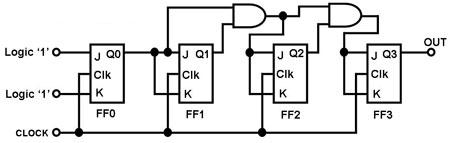
The circuit in Figure 1 is a 4-bit asynchronous counter, also known as a ripple counter. It consists of four J-K flip-flops with their J and K inputs connected to logic 1. This configuration causes the output of each J-K...
Divide-By-Odd-Number Counter
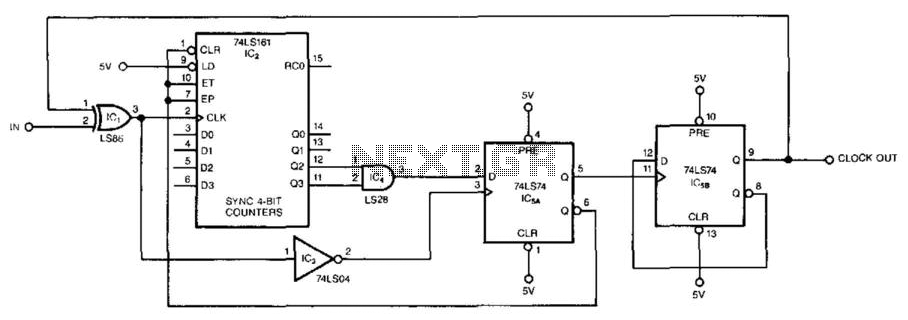
This circuit symmetrically divides an input by virtually any odd number. The circuit contains n + 1 clocks to achieve the desired divisor. By selecting the proper n, which is the decoded output of the 74LS161 counter, divisors from 3...
1Hz Timebase For Readout And Counter Applications
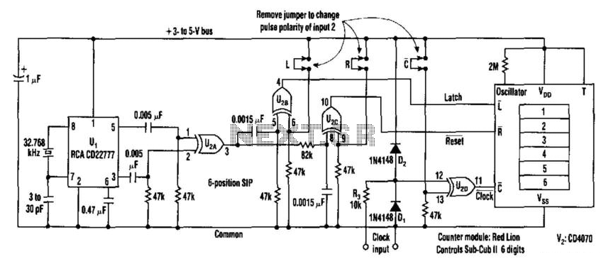
This counter facilitates the direct readout of frequency-generating equipment by incorporating a 1-Hz time base to latch, reset, and condition the count signal. The design allows for the selection of either polarity. By differentiating, inverting, and ORing the clock pulses...
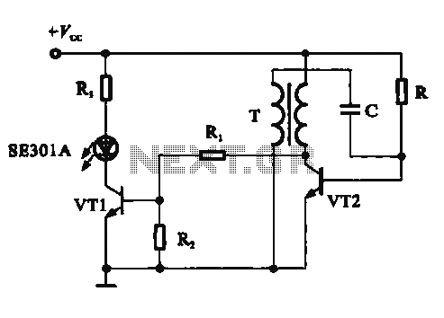
Pulse signal generating circuit and display
This circuit demonstrates a dynamic AC signal level display drive, which can be utilized for audio level display purposes. The AC signal detection and drive control are achieved using the BA6124 integrated circuit, along with five external colored light-emitting diodes...
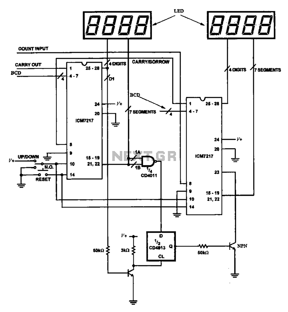
8-bit digital counter circuit
Figure 8 illustrates a potential digital counter circuit. This circuit employs two ICM7217 integrated circuits, with each controlling four digital display tubes.
The digital counter circuit primarily utilizes the ICM7217, a highly integrated chip designed for driving seven-segment displays. Each ICM7217...
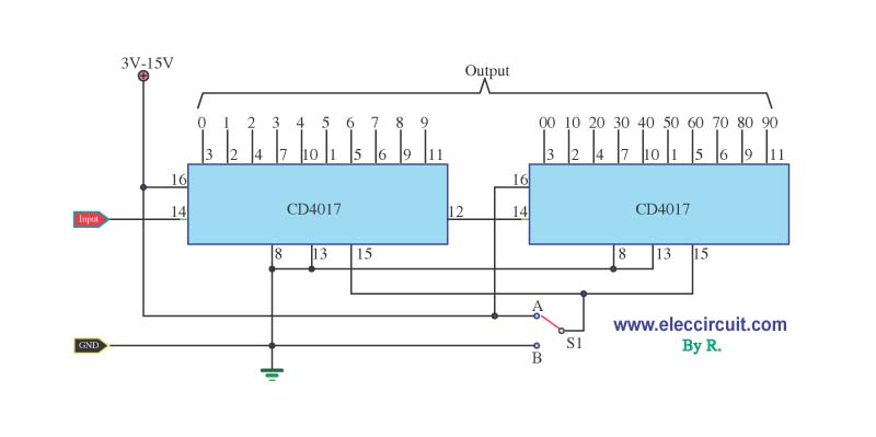
0-99 counter by IC 4017G—2
When designing a counter circuit that counts from 0 to 99, an effective approach is to utilize the IC LM4017, which is a decade counter.
The LM4017 is a CMOS decade counter capable of counting from 0 to 9, and it...
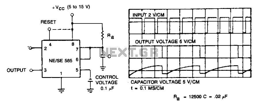
Frequency divider
If the input frequency is known, the timer can be utilized as a frequency divider by adjusting the duration of the timing cycle. The figure illustrates the waveforms of the timer when employed as a divide-by-three circuit. This application leverages...
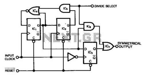
Divide-By-2-Or-3 Circuit
This circuit generates a symmetrical waveform by dividing the input frequency by either 2 or 3. The Divide Select input governs the division factor. When the Divide Select input is high, flip-flops IC1 and IC2, along with the associated gates,...
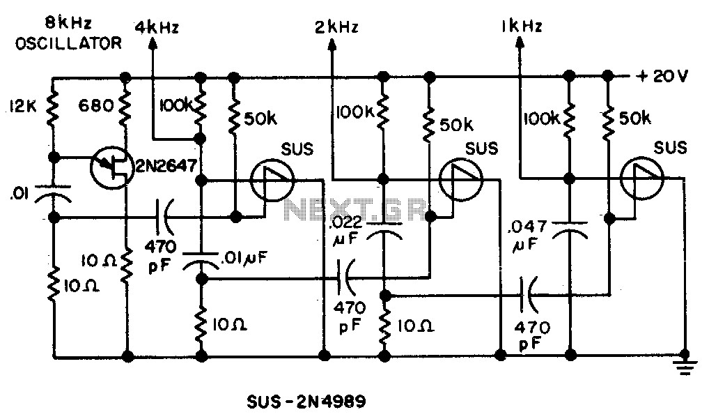
Frequency divider
Spikes in the center of a sawtooth wave are eliminated in this circuit by triggering at specific intervals.
This circuit is designed to mitigate unwanted spikes that occur in the center of a sawtooth waveform. The sawtooth wave, characterized by its...