


When abstract logic circuits get translated to the electrical equivilant how are conversions from 0 to 1 handled
#logic gates
#NOT gate
#binary signals
#voltage levels
#power sourcing
#digital electronics
#circuit theory
#signal conversion
#boolean logic
#electrical equivalence
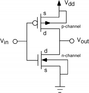
Description: The fundamental issue presented is the perception that logic gates in a circuit seem to generate power from nothing, which contradicts the principles of physics. For instance, consider two NOT gates connected in series. It appears that the first NOT gate interrupts the power supply to the second NOT gate, which seemingly generates new power from nowhere and transmits it onward. The only plausible explanation involves the assumption that every gate in the circuit is directly linked to a power source. The closest understanding revolves around the concept of changing the signal from "high" to "low." However, this raises the question of how a NOT gate can convert a low signal to a high one without drawing from a power source. The inquiry ultimately seeks to understand how logic gates can transform a 0 to a 1 without breaching the law of conservation of energy.
Logic gates are fundamental building blocks of digital circuits, functioning as electronic switches that manipulate binary signals. A NOT gate, also known as an inverter, takes a single input and produces an output that is the logical negation of that input. In a digital logic circuit, a high voltage level (often represented as a '1') and a low voltage level (represented as a '0') correspond to the binary states. The operation of a NOT gate does not create energy; rather, it alters the state of the input signal.
When a NOT gate receives a low signal (0), it outputs a high signal (1) by utilizing a power supply connected to the circuit. The power source provides the necessary energy, allowing the NOT gate to change the signal state. This process does not violate the conservation of energy principle, as the energy required to produce the high output signal comes directly from the power supply, not from the gate itself.
In a logic circuit, each gate is designed to operate within a defined voltage range, and the transitions between states are achieved through the manipulation of electrical signals. The apparent "magic" of signal conversion is merely a result of the gate's design and the underlying electrical principles that govern its operation. The conversion of signals is facilitated by semiconductor materials, which allow for the controlled flow of current, enabling the gates to perform their logical functions efficiently while adhering to the laws of physics.
Understanding the role of power sources and the behavior of electronic components is crucial for grasping how logic gates function without creating energy from nothing. The interaction of voltages, the arrangement of components, and the inherent properties of materials all contribute to the effective operation of digital circuits.The basic problem for me is that gates on a logic circuit appear to be creating power from nothing, which is impossible. For example imagine two NOT gates connected in sequence: To my uninitiated mind what seems to be happening is that the first NOT gate cuts the power to the second NOT gate, which responds by magically conjuring new power out of thin air and sending it on it`s way.
The only explanation I can come up with feels a bit redundant and absurd (That every single gate on the diagram is implied to be directly connected to a power source) The closest I`ve come to an answer is something to do with changing the "signal" from "high" to "low" but again, I`m not familiar enough with the language. It still suffers from the same problem, if you`ve got a low signal how is it that a NOT gate can turn it into a high one without directly drawing on a power source To wrap up and present the question in all it`s rookie glory: How do logic gates physically convert 0 to 1 without violating the law of conservation of energy
Logic gates are fundamental building blocks of digital circuits, functioning as electronic switches that manipulate binary signals. A NOT gate, also known as an inverter, takes a single input and produces an output that is the logical negation of that input. In a digital logic circuit, a high voltage level (often represented as a '1') and a low voltage level (represented as a '0') correspond to the binary states. The operation of a NOT gate does not create energy; rather, it alters the state of the input signal.
When a NOT gate receives a low signal (0), it outputs a high signal (1) by utilizing a power supply connected to the circuit. The power source provides the necessary energy, allowing the NOT gate to change the signal state. This process does not violate the conservation of energy principle, as the energy required to produce the high output signal comes directly from the power supply, not from the gate itself.
In a logic circuit, each gate is designed to operate within a defined voltage range, and the transitions between states are achieved through the manipulation of electrical signals. The apparent "magic" of signal conversion is merely a result of the gate's design and the underlying electrical principles that govern its operation. The conversion of signals is facilitated by semiconductor materials, which allow for the controlled flow of current, enabling the gates to perform their logical functions efficiently while adhering to the laws of physics.
Understanding the role of power sources and the behavior of electronic components is crucial for grasping how logic gates function without creating energy from nothing. The interaction of voltages, the arrangement of components, and the inherent properties of materials all contribute to the effective operation of digital circuits.The basic problem for me is that gates on a logic circuit appear to be creating power from nothing, which is impossible. For example imagine two NOT gates connected in sequence: To my uninitiated mind what seems to be happening is that the first NOT gate cuts the power to the second NOT gate, which responds by magically conjuring new power out of thin air and sending it on it`s way.
The only explanation I can come up with feels a bit redundant and absurd (That every single gate on the diagram is implied to be directly connected to a power source) The closest I`ve come to an answer is something to do with changing the "signal" from "high" to "low" but again, I`m not familiar enough with the language. It still suffers from the same problem, if you`ve got a low signal how is it that a NOT gate can turn it into a high one without directly drawing on a power source To wrap up and present the question in all it`s rookie glory: How do logic gates physically convert 0 to 1 without violating the law of conservation of energy
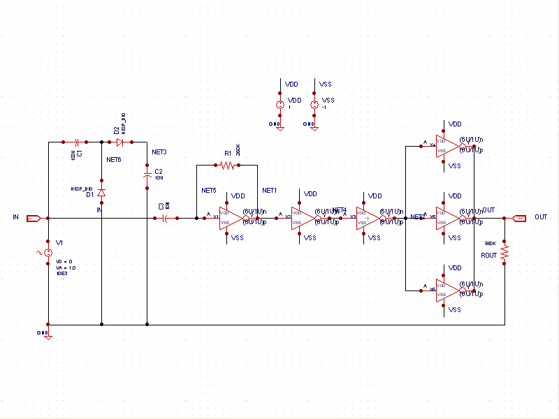
Sine to Square Wave Converter
This schematic example demonstrates a sinusoidal voltage input at a frequency of 10 kHz, which is converted to a square wave using an inverter-based circuit. The VDD and VSS rails are connected to +1V and -1V, respectively. The control file...
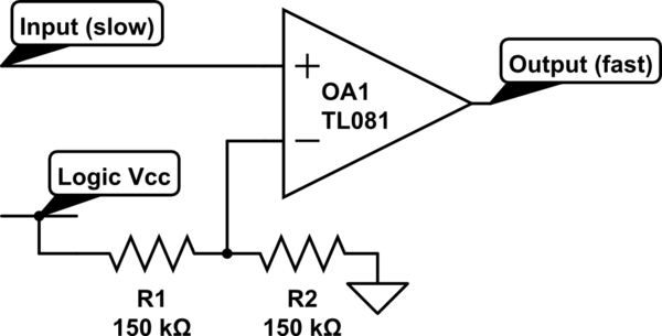
Logic Circuits Vs Transistor Power Circuits
Invert a signal to drive FETs with rapid rise and fall times. It was suggested to use an inverter (not a chip) instead of logic chips, which are designed to be either fully ON or OFF. The individual has prior...
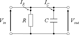
Circuit Theory/All Chapters
This wikibook serves as an introductory text about electric circuits, covering the fundamentals of electric circuit theory, circuit analysis, and circuit design. It is intended as a companion reference for first-year Electrical Engineering undergraduates. Topics include AC and DC circuits,...
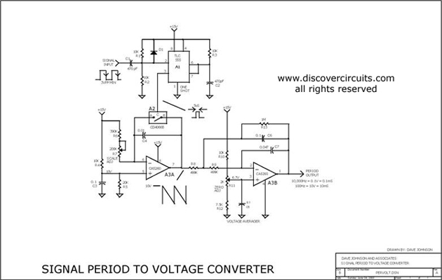
PULSE PERIOD TO VOLTAGE CONVERTER
This circuit is designed to convert a square wave input signal into a voltage output. The voltage produced is proportional to the time interval between the edges (period) of the signal, rather than its frequency. The operational range of the...
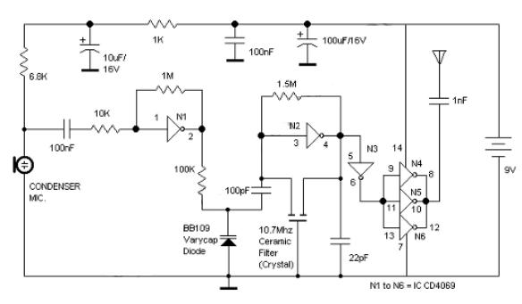
Logic Gates FM Transmitter Circuit
Logic Gates FM Transmitter Circuit Electronic Circuit Schematic Wiring Diagram.
The FM transmitter circuit utilizing logic gates is a fundamental electronic design that operates by modulating a carrier frequency with an audio signal. This circuit typically consists of various logic gates...
Sine to Square Wave Converter
This schematic example demonstrates a sinusoidal voltage input at a frequency of 10 kHz, which is converted to a square wave using an inverter-based circuit. The VDD and VSS rails are connected to +1V and -1V, respectively. The control file...
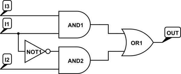
Help with designing a circuit with logic gates
There are integrated circuits that contain AND, OR, and NOT gates. The inquiry revolves around the existence of a single chip that encompasses all the required logic gates. If such a chip does not exist, specific alternatives should be considered....
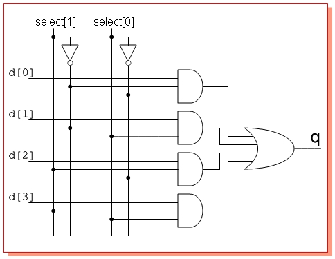
electrical engineering logic gates
Design a circuit with four single-bit inputs X, Y, T, and Z, and a single-bit output E. A two-bit control code word S0S1 determines which of the four inputs is sent to the output (the selection code is not unique)....
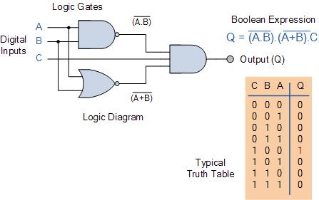
Combinational Logic Circuits using Logic Gates
Electronics tutorial on combinational logic circuits that utilize logic gates to create multiplexers, encoders, and solid-state switches.
Combinational logic circuits are fundamental components in digital electronics, characterized by their ability to produce outputs based solely on the current inputs, without any...