


Hand Steadiness electronic Game
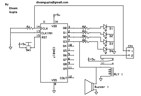
Description: The Hand Steadiness Tester is a game which tests the steadiness of your hand. The player has to take the ring from one end to another end without touching it to the wire. In this the player gets 4 turns. If the player touches the wire 4 times he has to reset the game & start the whole game from the beginning. This project consists of IC 4017, a Buzzer, a Relay, some resistors, a Push button and 4 LEDs. There is also a PCB layout given. There are many types of Hand Steadiness Testers which are very simple. This New Hand Steadiness Tester is more advanced. When the player touches the wire one time 1st LED turns on. When he touches 2nd time the 2nd LED turns on. When he touches 3rd time the 3rd LED turns on. When he touches 4th time the 4th LED turns on & the buzzer starts beeping. To stop the buzzer he has to push the reset button. This is IC 4017. Q0 -Q3 are connected to LEDs through 330ohms resistors. Q3 is also connected to a buzzer & a relay. When we touch the wire with the ring, a positive current flows to pin 14. When the player touches the wire 4 times, the relay gets on; this breaks the contact between the ring and pin 14 of IC. So after that the buzzer keeps beeping. When we push the reset button, the IC resets and the buzzer, the LED & the relay gets off.
The Hand Steadiness Tester is an interactive electronic device designed to evaluate a user's hand stability by navigating a conductive ring along a wire without making contact. The primary components of this circuit include the CD4017 decade counter IC, which is pivotal in managing the LED indicators and triggering the buzzer and relay based on the game progress.
The circuit operates by utilizing the ring as a conductive object that completes a circuit when it touches the wire. Each time the wire is touched, a positive voltage is sent to pin 14 of the CD4017, which increments the output state. The outputs Q0 through Q3 are connected to four individual LEDs via 330-ohm resistors, illuminating one LED for each touch, thereby providing visual feedback to the player. Upon the fourth touch, the output at Q3 activates, which simultaneously triggers a buzzer and a relay.
The buzzer emits a sound to indicate that the player has failed to navigate the ring successfully four times, prompting the need for a reset. The relay serves a dual purpose; it disconnects the conductive path between the ring and pin 14 of the IC, ensuring that further touches do not affect the game state until it is reset. The reset function is initiated by pressing a push button, which clears the IC’s count and turns off the buzzer, LEDs, and relay, allowing the player to start the game anew.
The PCB layout for the Hand Steadiness Tester has been designed to accommodate all components efficiently, ensuring that the connections are stable and reducing the risk of interference or short circuits. This advanced version of the Hand Steadiness Tester enhances the user experience by providing immediate feedback and a clear mechanism for game reset, making it a more engaging and challenging game compared to simpler versions.The Hand Steadiness Tester is a game which tests the steadiness of your hand. The player has to take the ring from one end to another end without touching it to the wire. In this the player gets 4 turns. If the player touches the wire 4 times he has to reset the game & start the whole game from the beginning. This project consists of IC 4017, a Buzzer, a Relay, some resistors, a Push button and 4 LEDs. There is also a PCB layout given. There are many types of Hand Steadiness Testers which are very simple. This New Hand Steadiness Tester is more advanced. When the player touches the wire one time 1st LED turns on. When he touches 2nd time the 2nd LED turns on. When he touches 3rd time the 3rd LED turns on. When he touches 4th time the 4th LED turns on & the buzzer starts beeping. To stop the buzzer he has to push the reset button. This is IC 4017. Q0 -Q3 are connected to LEDs through 330ohms resistors. Q3 is also connected to a buzzer & a relay. When we touch the wire with the ring, a positive current flows to pin 14. When the player touches the wire 4 times, the relay gets on; this breaks the contact between the ring and pin 14 of IC. So after that the buzzer keeps beeping. When we push the reset button, the IC resets and the buzzer, the LED & the relay gets off.
The Hand Steadiness Tester is an interactive electronic device designed to evaluate a user's hand stability by navigating a conductive ring along a wire without making contact. The primary components of this circuit include the CD4017 decade counter IC, which is pivotal in managing the LED indicators and triggering the buzzer and relay based on the game progress.
The circuit operates by utilizing the ring as a conductive object that completes a circuit when it touches the wire. Each time the wire is touched, a positive voltage is sent to pin 14 of the CD4017, which increments the output state. The outputs Q0 through Q3 are connected to four individual LEDs via 330-ohm resistors, illuminating one LED for each touch, thereby providing visual feedback to the player. Upon the fourth touch, the output at Q3 activates, which simultaneously triggers a buzzer and a relay.
The buzzer emits a sound to indicate that the player has failed to navigate the ring successfully four times, prompting the need for a reset. The relay serves a dual purpose; it disconnects the conductive path between the ring and pin 14 of the IC, ensuring that further touches do not affect the game state until it is reset. The reset function is initiated by pressing a push button, which clears the IC’s count and turns off the buzzer, LEDs, and relay, allowing the player to start the game anew.
The PCB layout for the Hand Steadiness Tester has been designed to accommodate all components efficiently, ensuring that the connections are stable and reducing the risk of interference or short circuits. This advanced version of the Hand Steadiness Tester enhances the user experience by providing immediate feedback and a clear mechanism for game reset, making it a more engaging and challenging game compared to simpler versions.The Hand Steadiness Tester is a game which tests the steadiness of your hand. The player has to take the ring from one end to another end without touching it to the wire. In this the player gets 4 turns. If the player touches the wire 4 times he has to reset the game & start the whole game from the beginning. This project consists of IC 4017, a Buzzer, a Relay, some resistors, a Push button and 4 LEDs. There is also a PCB layout given. There are many types of Hand Steadiness Testers which are very simple. This New Hand Steadiness Tester is more advanced. When the player touches the wire one time 1st LED turns on. When he touches 2nd time the 2nd LED turns on. When he touches 3rd time the 3rd LED turns on. When he touches 4th time the 4th LED turns on & the buzzer starts beeping. To stop the buzzer he has to push the reset button. This is IC 4017. Q0 -Q3 are connected to LEDs through 330ohms resistors. Q3 is also connected to a buzzer & a relay. When we touch the wire with the ring, a positive current flows to pin 14. When the player touches the wire 4 times, the relay gets on; this breaks the contact between the ring and pin 14 of IC. So after that the buzzer keeps beeping. When we push the reset button, the IC resets and the buzzer, the LED & the relay gets off.
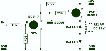
12V Relay on 6V power supply
This circuit allows a 12v relay to operate on a 6v or 9v supply. Most 12v relays need about 12v to "pull-in" but will "hold" on about 6v. The 220u charges via the 2k2 and bottom diode. When an input...
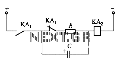
Delaying the release of DC relay circuit
To fulfill the requirements of a control loop, it is often necessary to utilize an electromagnetic relay or a transistor relay to either accelerate or delay an action, thereby forming an acceleration or delay circuit. The circuit depicted in Figure...
Delaying the release of DC relay circuit
To fulfill the requirements of a control loop, it is often necessary to utilize an electromagnetic relay or a transistor relay to either accelerate or delay an action, thereby forming an acceleration or delay circuit. The circuit depicted in Figure...
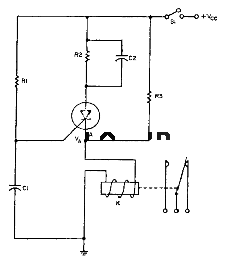
Relay driver
The relay operates for a specific duration, td, after power is applied, followed by an operating time, tc. The SCR activates when the voltage across capacitor Ci reaches a threshold voltage, VA. This action energizes the relay, which remains activated...
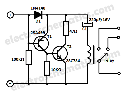
Control Circuits
This low current relay circuit is designed for use in battery-operated electronic devices. Its operating current is in microamperes (µA). This is achieved by using a bistable relay and incorporating additional components to enable the relay to function like a...
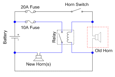
GS500 Horn
A relay is an electrically operated switch that utilizes a coil to create magnetism, which closes the contacts of the switch. In automotive applications, a 12V signal through the coil allows 12V to flow through the switch contacts. The advantage...
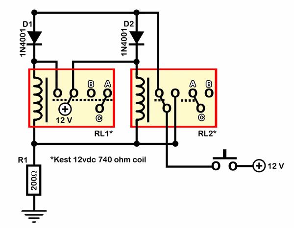
build relay toggle switch
Half of RL1 and RL2 manage the switching mechanism, while the other half connects to an application. The relays operate at 200 ohms above ground, with one terminal referenced to positive voltage, which deactivates them. RL1, when off, applies a...
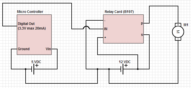
Common ground for different voltages in relay circuit
The objective is to control a 12 VDC device (on/off) from a microcontroller using a relay card. The relay requires a 12 VDC operating power supply.
To achieve the control of a 12 VDC device using a microcontroller and a relay...
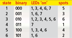
dicing with leds
Every DIY enthusiast creates their own electronic dice using LEDs as indicators. This eliminates the need to physically throw the dice; instead, a button press activates the roll. The circuit design ensures fairness by preventing manipulation of the outcome, much...