


Who Press First Educational Game
#NAND IC
#Latch IC
#button press
#game
#electronics education
#logic circuit
#educational project
#digital logic
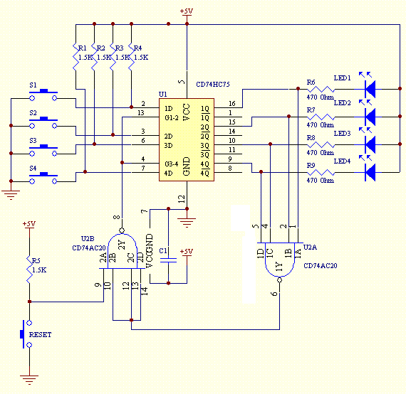
Description: This electronics educational game utilizes a NAND integrated circuit (IC), a latch IC, and several peripheral components to create a project that can identify which of the four individuals presses the button first.
The project is designed to engage users in a hands-on learning experience about digital electronics. It incorporates a NAND gate, which is a fundamental building block in digital logic design, to perform the necessary logical operations. The latch IC is employed to store the state of the button presses, ensuring that the project can accurately determine which participant was the quickest to respond.
The circuit typically includes four push-button switches, each representing one of the four participants. When a button is pressed, it sends a signal to the NAND gate, which processes the input and controls the output to the latch IC. The latch then retains the state of the first button pressed, effectively locking in the result until it is reset.
Additional components may include resistors to limit current, capacitors for debouncing the button presses, and possibly LEDs to provide visual feedback indicating which button was pressed first. A reset mechanism, such as a dedicated reset button or an automatic reset after a predetermined time, can be incorporated to allow for multiple rounds of play.
This educational game serves as an excellent platform for teaching concepts such as digital logic, timing, and state retention in electronic circuits, making it a valuable tool for both students and educators in the field of electronics.This electronics educational game uses a NAND IC, a Latch IC and a few peripheral components to construct a project that is able to tell who among the four person press the button first
The project is designed to engage users in a hands-on learning experience about digital electronics. It incorporates a NAND gate, which is a fundamental building block in digital logic design, to perform the necessary logical operations. The latch IC is employed to store the state of the button presses, ensuring that the project can accurately determine which participant was the quickest to respond.
The circuit typically includes four push-button switches, each representing one of the four participants. When a button is pressed, it sends a signal to the NAND gate, which processes the input and controls the output to the latch IC. The latch then retains the state of the first button pressed, effectively locking in the result until it is reset.
Additional components may include resistors to limit current, capacitors for debouncing the button presses, and possibly LEDs to provide visual feedback indicating which button was pressed first. A reset mechanism, such as a dedicated reset button or an automatic reset after a predetermined time, can be incorporated to allow for multiple rounds of play.
This educational game serves as an excellent platform for teaching concepts such as digital logic, timing, and state retention in electronic circuits, making it a valuable tool for both students and educators in the field of electronics.This electronics educational game uses a NAND IC, a Latch IC and a few peripheral components to construct a project that is able to tell who among the four person press the button first
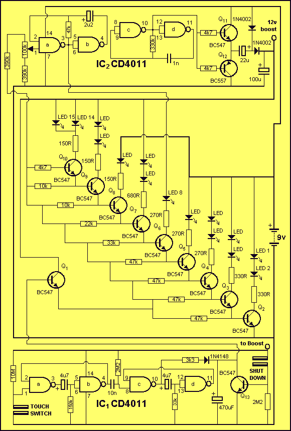
HANGMAN schematic
Everybody likes re-discovering something they did years ago. Here's a game we all played at school. Possibly under the name of HANG THE BUTCHER. The game is quite simple. One player thinks of a word and writes down the number...
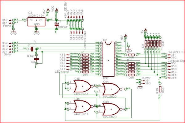
Steady Hands Game Project
A "Steady Hands Game" was developed to meet the requirement for a cub-scout event. Initially prototyped on a homework board, a more permanent version of the game was created for educational purposes. The final version features a wand (black) that...
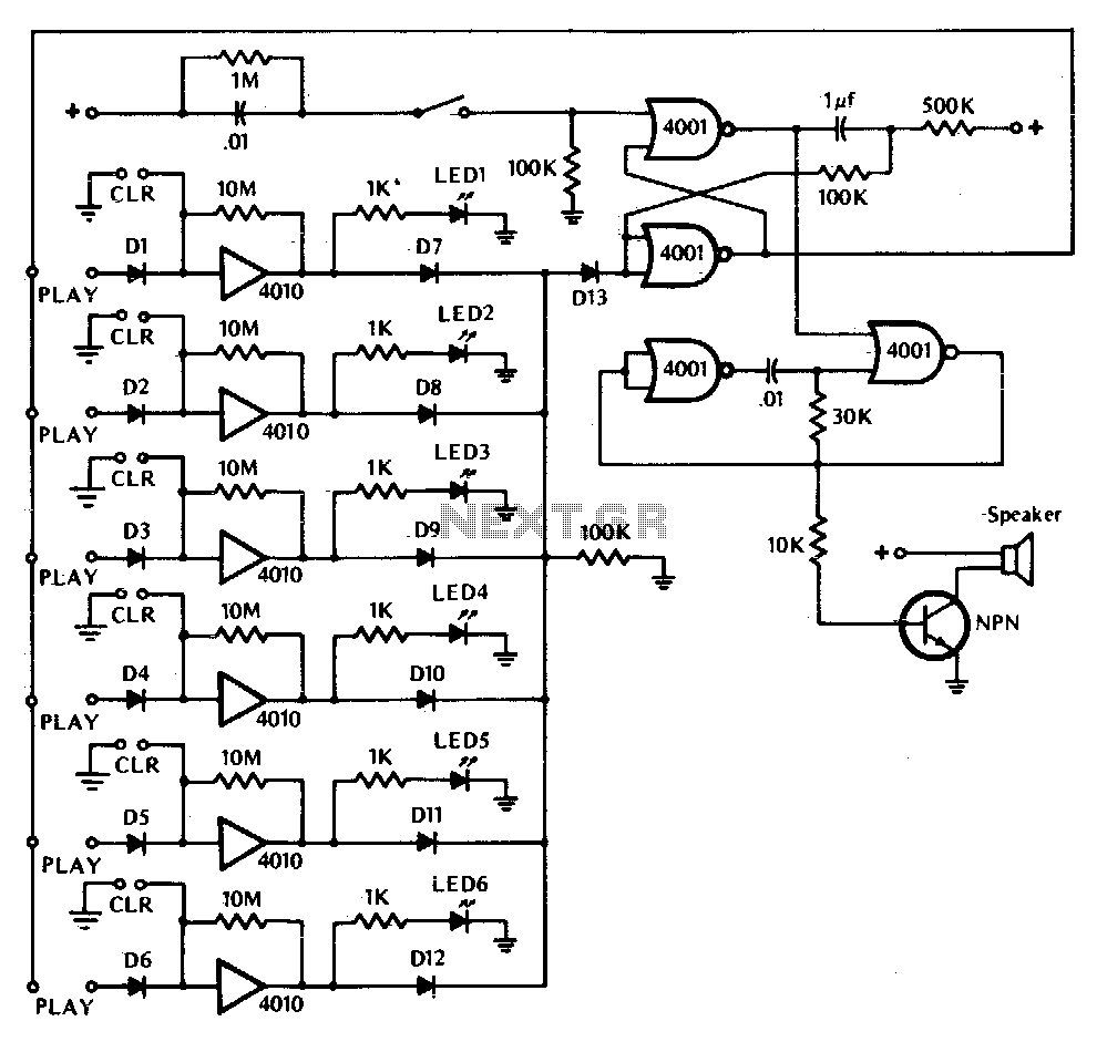
Ready set goi
This game tests a player's reaction time. It is activated by closing switch SI, which starts the tone generator and arms the circuit. The touchplate, labeled PLAY in the diagram, consists of two metal strips about 1/16th inch apart. The...
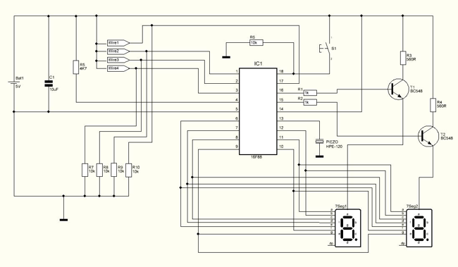
Bomb Deactivation Game
Should I cut the blue wire... or the red...? This is a very common phrase in many movies when the action hero has a bomb in front of him with little time left and he has to choose which wire...
Bomb Deactivation Game
Should I cut the blue wire... or the red...? This is a very common phrase in many movies when the action hero has a bomb in front of him with little time left and he has to choose which wire...
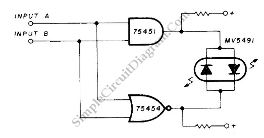
Coincidence Detector for Logic Signals
This is a coincidence detector circuit. This circuit is very useful for monitoring complex logic circuits. This circuit has two inputs, A and B. If A and B are...
The coincidence detector circuit is designed to identify when two input signals,...
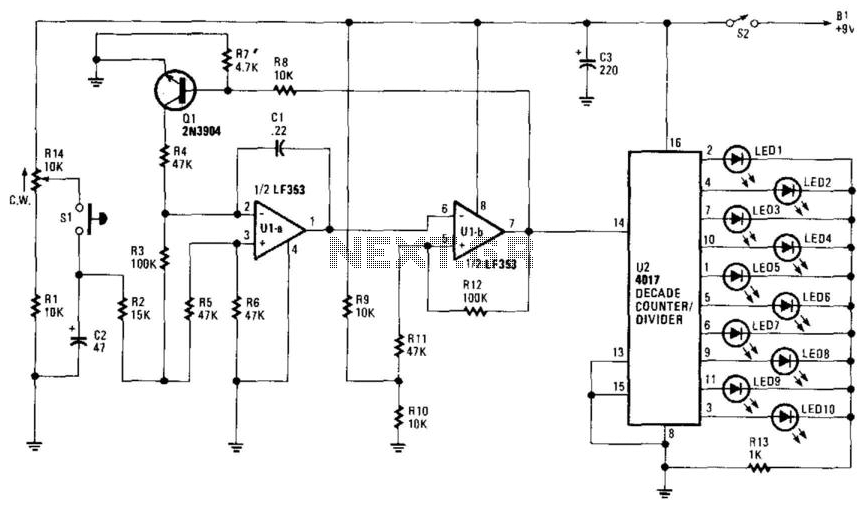
Electronic Roulette Game
R14 is configured to establish an initial "starting" speed for the oscillators U1A and U1B. As capacitor C2 charges, the oscillation gradually slows down during the discharging phase of C2, creating a roulette-wheel effect on LED S1 through resistor R10....
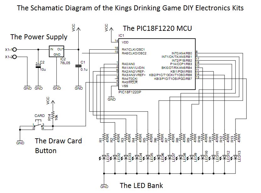
The Electronic Kings drinking game circuit!
This circuit was designed approximately four months ago and has been developed into a kit for others to use.
The circuit in question appears to be a well-thought-out design that has been packaged into a kit format, making it accessible for...
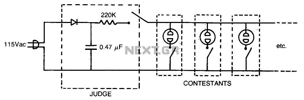
Who is first
This circuit is designed for use in a question-and-answer party game. The first button pressed ionizes a neon bulb, causing the DC voltage across the parallel-connected neon bulbs (representing other contestants) to drop below the ionization threshold, thereby clearly identifying...