


Avramenko’s Plug
#Avramenko
#single wire transmission
#high voltage
#diodes
#capacitor
#flash tube
#auto ignition coil
#energy transmission
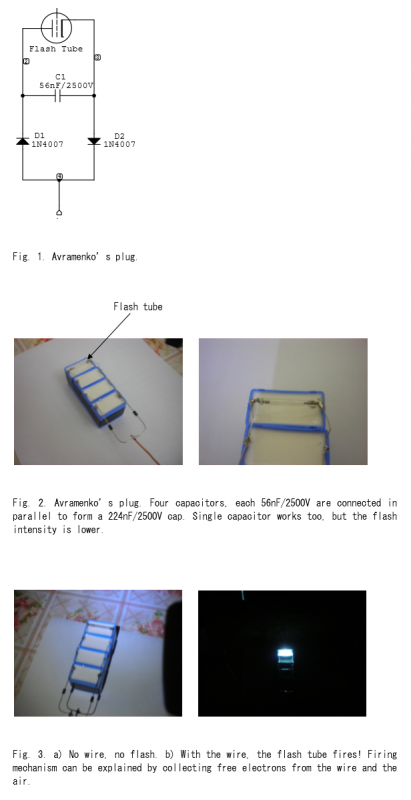
Description: Avramenko is a Russian scientist who invented a plug designed to transmit electrical energy over a single wire. This simple circuit comprises two diodes, one capacitor, and a flash tube. The high-voltage (HV) terminal connects to the HV output of an auto ignition coil. The positive HV pulse charges capacitor C1 through diode D1, while diode D2 remains off during this process. When the pulse is off, diode D1 also becomes off, allowing the charged capacitor to discharge through the flash tube. When there is no trigger wire, the flash tube will not fire. However, wrapping a wire around the flash tube and extending it into the air by approximately 15 cm will enable the tube to fire effectively.
The described circuit operates on the principle of energy transfer through a single wire, leveraging the characteristics of diodes and capacitors for efficient energy storage and release. The auto ignition coil serves as a high-voltage source, generating a pulse that is crucial for charging the capacitor. Diode D1 functions as a forward-biased component during the charging phase, allowing current to flow into the capacitor and storing electrical energy. Meanwhile, diode D2 remains reverse-biased, preventing any current from bypassing the intended path during this phase.
Once the charging pulse ceases, diode D1 switches off, and the stored energy in capacitor C1 is released through the flash tube. This discharge produces a high-intensity light flash, which is the primary function of the circuit. The operation of the flash tube is contingent upon the presence of a trigger wire; without it, the circuit cannot initiate the discharge process. The introduction of a wire wrapped around the flash tube enhances its ability to fire by potentially inducing a magnetic field that triggers the tube under certain conditions.
This circuit exemplifies a practical application of electronic components in energy transmission and light generation, showcasing the innovative approach taken by Avramenko to simplify electrical energy transfer. The design can be further explored for applications in various fields, including automotive lighting, signal generation, and other high-voltage applications where efficient energy transfer is required.Avramenko is a Russian scientist and invented the plug shown in Fig. 1 to transmit electrical energy over a single wire. It’s a simple circuit consisting of two diodes, one capacitor, and a flash tube. The high-voltage (HV) terminal is connected to the HV output of an auto ignition coil. The + HV pulse charges C1 through D1. D2 is OFF during this operation. When the pulse is OFF, D1 will be OFF, and the charged capacitor will be discharged through the flash tube.
The described circuit operates on the principle of energy transfer through a single wire, leveraging the characteristics of diodes and capacitors for efficient energy storage and release. The auto ignition coil serves as a high-voltage source, generating a pulse that is crucial for charging the capacitor. Diode D1 functions as a forward-biased component during the charging phase, allowing current to flow into the capacitor and storing electrical energy. Meanwhile, diode D2 remains reverse-biased, preventing any current from bypassing the intended path during this phase.
Once the charging pulse ceases, diode D1 switches off, and the stored energy in capacitor C1 is released through the flash tube. This discharge produces a high-intensity light flash, which is the primary function of the circuit. The operation of the flash tube is contingent upon the presence of a trigger wire; without it, the circuit cannot initiate the discharge process. The introduction of a wire wrapped around the flash tube enhances its ability to fire by potentially inducing a magnetic field that triggers the tube under certain conditions.
This circuit exemplifies a practical application of electronic components in energy transmission and light generation, showcasing the innovative approach taken by Avramenko to simplify electrical energy transfer. The design can be further explored for applications in various fields, including automotive lighting, signal generation, and other high-voltage applications where efficient energy transfer is required.Avramenko is a Russian scientist and invented the plug shown in Fig. 1 to transmit electrical energy over a single wire. It’s a simple circuit consisting of two diodes, one capacitor, and a flash tube. The high-voltage (HV) terminal is connected to the HV output of an auto ignition coil. The + HV pulse charges C1 through D1. D2 is OFF during this operation. When the pulse is OFF, D1 will be OFF, and the charged capacitor will be discharged through the flash tube.
When there is no trigger wire, the flash tube won’t fire! When I wrap a wire around the flash tube and extend it into the air by about 15 cm, the tube will fire nicely. By 4beowulf7 - [email protected]

High Voltage Generation For Xenon Tube Applications
Power demand in portable designs can require, in specific applications, more than 1 A. A method involves paralleling two DC to DC converters on the same load instead of using a single higher current converter with a lower switching frequency....

Capacitor-discharge-high-voltage-generator
A step-down transformer T1 reduces the incoming line voltage to approximately 48 Vac, which is then rectified by diode D1. The resulting direct current charges capacitor C1 through a current-limiting resistor R1 to a voltage level set by R4. When...
High Voltage Pulse Generator Electronic Circuit
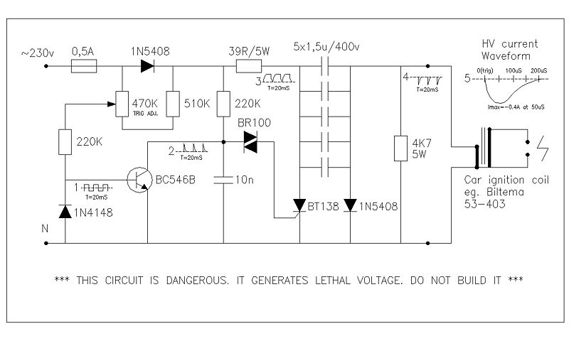
This circuit generates high voltage pulses from a 230 VAC line voltage. The drive end's swing comparator circuit was developed by the creator of this page. The working end is derived from a stroboscope trigger supply circuit. All circuits utilizing...
Nixie low voltage PSU
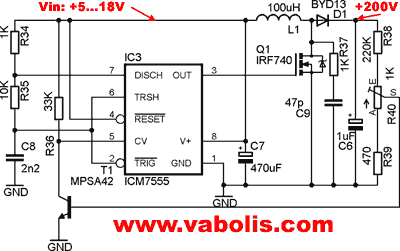
Occasionally, a small high-voltage power supply is required for various projects without the need for specialized transformers or specific chips. A simple circuit diagram for a classical step-up converter based on the widely used 555 timer was found online. The...
Preregulated-high-voltage-supply
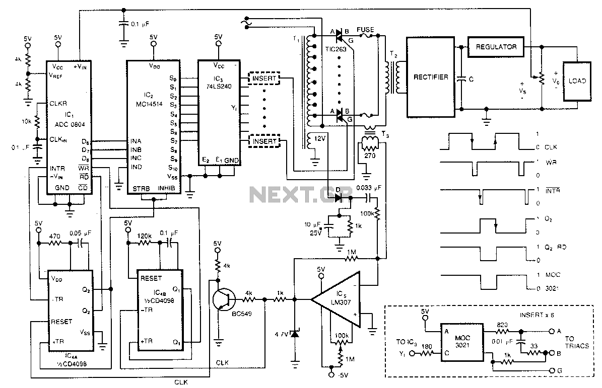
One of the control circuit's triacs selects the tap on the main transformer T1, which provides the proper preregulated voltage to the secondary regulator. T2 and its associated components comprise the secondary regulator. The ADC 0804, IC1, digitizes a voltage...
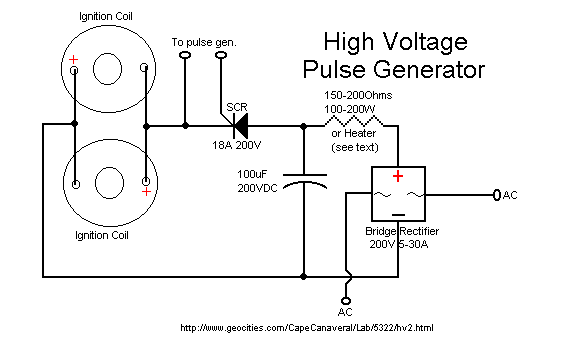
60kv ignition coil driver circuit
The ignition coil driver circuit described is a highly regarded design, reportedly created by Jochen Kronjaeger. It is intended to operate from a 230V source, although a modified version can function effectively at 120V. The circuit requires two ignition coils...
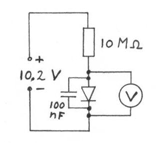
Diodes for crystal receivers
Diodes with a low voltage drop also exhibit a high reverse current (leakage current), which places a heavier load on the detector circuit, reducing the quality factor (Q) of the circuit and consequently lowering the voltage across the LC circuit....
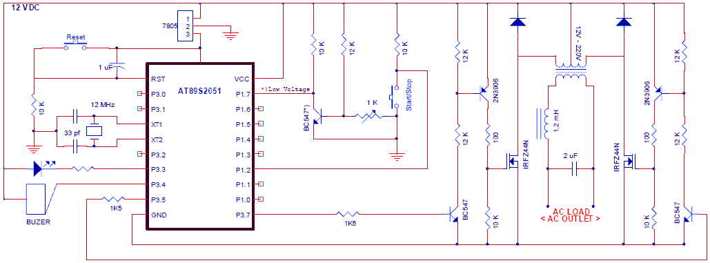
Gray Tube Replication 75
The circuit utilizes a combination of high-voltage diodes, with plans to replace the current three high-voltage diodes with 1200-volt, 6-amp diodes. A basic transistor circuit and a square wave generator are employed to trigger a relay, operating optimally at around...
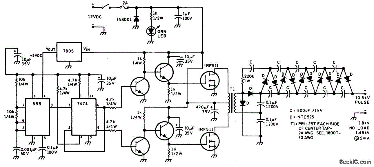
HELIUM NEON LASER SUPPLY
This figure illustrates a method for generating a momentary 10-kV voltage pulse to initiate plasma discharge across a laser tube. A diode voltage-multiplier circuit is connected in series with the main supply, obtaining its input power from one of the...