


Overunity Joule Thief Circuit
#joule thief
#overunity
#energy harvesting
#physics
#Steven E. Jones
#circuit design
#low voltage
#experimental
#free energy
#power efficiency
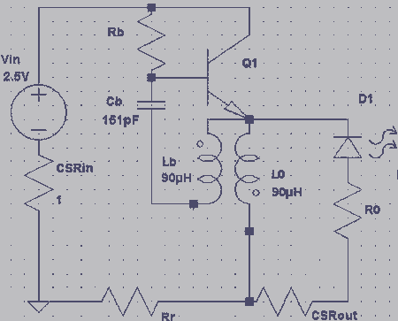
Description: Retired Physics Professor Steven E. Jones is working on a simple overunity circuit that he has observed achieving up to 20 times overunity. This circuit is a variation of the Joule Thief or a blocking oscillator. His design incorporates an LC circuit that feeds into the base of the transistor.
The described overunity circuit utilizes principles derived from the Joule Thief design, which is known for its ability to extract energy from low-voltage sources, such as depleted batteries. The key components of this circuit include an inductor (L), a capacitor (C), and a transistor, which work together to create a feedback mechanism that enhances energy transfer.
In the circuit configuration, the LC circuit serves as an oscillator, generating a resonant frequency that can amplify the input energy. The inductor stores energy in its magnetic field when current flows through it, while the capacitor stores energy in its electric field. When the circuit reaches resonance, the oscillation can lead to a significant increase in voltage and current at the output compared to the input, potentially achieving overunity operation.
The transistor acts as a switch, controlling the flow of current through the circuit. When the LC circuit oscillates, it provides a pulsed signal to the base of the transistor, allowing it to rapidly turn on and off. This switching action can lead to a higher efficiency in energy transfer, as the transistor can amplify the current flowing through the load connected to the circuit.
The circuit may also include additional components such as diodes for rectification, resistors for biasing, and capacitors for filtering, depending on the specific design requirements. Proper tuning of the LC circuit is essential to achieve the desired oscillation frequency and maximize the energy output.
Overall, this circuit represents an innovative approach to energy generation, leveraging established electronic principles to explore the potential for overunity performance. Further experimentation and refinement may yield valuable insights into its operational characteristics and efficiency.Retired Physics Professor, Steven E. Jones is working on a simple overunity circuit that he has seen go as high as 20 times overunity. The circuit is a derivation of the Joule Thief circuit or a blocking oscillator. His variation has an LC-circuit feeding into the base of the transistor.
The described overunity circuit utilizes principles derived from the Joule Thief design, which is known for its ability to extract energy from low-voltage sources, such as depleted batteries. The key components of this circuit include an inductor (L), a capacitor (C), and a transistor, which work together to create a feedback mechanism that enhances energy transfer.
In the circuit configuration, the LC circuit serves as an oscillator, generating a resonant frequency that can amplify the input energy. The inductor stores energy in its magnetic field when current flows through it, while the capacitor stores energy in its electric field. When the circuit reaches resonance, the oscillation can lead to a significant increase in voltage and current at the output compared to the input, potentially achieving overunity operation.
The transistor acts as a switch, controlling the flow of current through the circuit. When the LC circuit oscillates, it provides a pulsed signal to the base of the transistor, allowing it to rapidly turn on and off. This switching action can lead to a higher efficiency in energy transfer, as the transistor can amplify the current flowing through the load connected to the circuit.
The circuit may also include additional components such as diodes for rectification, resistors for biasing, and capacitors for filtering, depending on the specific design requirements. Proper tuning of the LC circuit is essential to achieve the desired oscillation frequency and maximize the energy output.
Overall, this circuit represents an innovative approach to energy generation, leveraging established electronic principles to explore the potential for overunity performance. Further experimentation and refinement may yield valuable insights into its operational characteristics and efficiency.Retired Physics Professor, Steven E. Jones is working on a simple overunity circuit that he has seen go as high as 20 times overunity. The circuit is a derivation of the Joule Thief circuit or a blocking oscillator. His variation has an LC-circuit feeding into the base of the transistor.
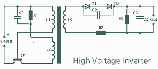
3V to high Joule Thief inverter circuit
A 3V to 1000V inverter circuit has been constructed, but it is not functioning as intended. The creator seeks expert assistance to identify potential errors in the circuit design. Additionally, there is uncertainty regarding the transformer construction, as the same...
Super Joule Thief
A compact Joule Thief circuit utilizes nine white LEDs, drawing approximately 250 mA at an input voltage of 1.5 V. During the video demonstration, the battery voltage was slightly below 1.3 V.
The Joule Thief circuit is a simple yet effective...

Selfrunning Free Energy 5 KW Kapanadze 4
The device features high-voltage (HV) insulation made of polystyrene. Incorporating ferrite may serve as a method to lower the frequency. However, using copper could lead to short circuits due to its interaction with radiant energy. It is noted that standard...
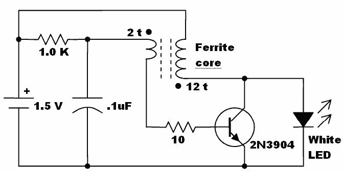
Ferrite Core Joule Thief circuit
Here is an idea for a voltage booster that enables the lighting of a white LED using a single AA cell. This presents an opportunity to utilize one of the ferrite cores and white LED holiday lights mentioned in previous...
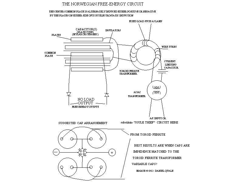
Joule Thief Circuit Explanations
Joule thief circuit along with videos, circuit diagrams, and explanations.
The Joule thief circuit is a minimalist boost converter designed to extract energy from low-voltage sources, such as depleted batteries. This circuit is particularly effective for powering small electronic devices,...
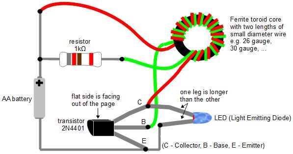
joule thief
The Joule Thief is an electronic circuit designed to utilize batteries that are typically deemed dead. A battery is often labeled "dead" when it can no longer power a specific device. However, the underlying issue is that the battery voltage...
Free energy generating coil
The disk magnets are attracted to each end of the power coil. The coil is pulse charged, causing the permanent magnetic field to push away from the center of the coil. When the electromagnetic field collapses in the coil, the...

Single cell 1.2 or 1.5V LED inverter Joule thief circuit
More:
The input data contains a brief description with no additional context or information provided.
In the realm of electronics, a circuit schematic typically serves as a visual representation of an electrical circuit. It illustrates the various components such as...
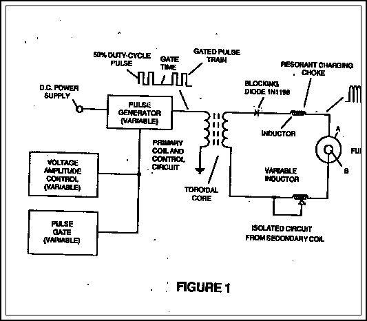
Free Energy Schematic
The fundamental concept involves a high-frequency, high-voltage, low-current signal that is rectified and subsequently utilized to charge a bank of high-value capacitors. These capacitors are then discharged in pulse mode for brief intervals, specifically in the nanosecond range, through a...