


Vladimir Utkins Free-Energy Secrets
#free-energy
#generator
#motor
#feedback loop
#Nikola Tesla
#electromagnetic
#electrical circuit
#energy system
Description: An ordinary energy system consists of a generator and a motor, which can be enhanced with an electric current feedback as illustrated in electrical circuit (a). In this scenario, once the system is initiated, it will decelerate and eventually stop due to friction, resistance, and other factors. Nikola Tesla proposed a feedback loop for the electromagnetic field, as depicted in case (b), where the system, once started, will continue to accelerate despite the presence of friction and resistance, provided that the phase of the electromagnetic feedback is positive and sufficiently large. For an electromagnetic field to exist within a motor, an energy input is necessary. Tesla indicated that a typical unipolar motor comprises a magnetized disk and a voltage applied between the axis and a point on the circumference of the disk, as shown in (a). Alternatively, a unipolar motor may consist of an external magnet and a metal disk with a voltage applied between the axis and a peripheral point on the disk, as illustrated in (b). Tesla modified this version of the unipolar motor by slicing the metal disk into helical sections. In this configuration, the current consumption generates an additional magnetic field along the axis of the disk. When the current-carrying wires are inclined in one direction, their magnetic field enhances the primary external magnetic field; conversely, tilting the wires in the opposite direction diminishes the external magnetic field. Therefore, the current flow can either amplify or reduce the external magnetic field of the unipolar motor. If a magnetic field feedback loop can be established for mechanical devices, it may also be feasible for solid-state devices such as coils and capacitors. Subsequent sections of this article focus on devices utilizing coils and capacitors. The examples provided are intended to facilitate comprehension of the underlying principles. Enhanced understanding can be achieved by examining the ferromagnetic shielding of the second coil in the transformer designed by Nikola Tesla. In this design, the ferromagnetic shield separates the first and second coils, enabling the shield to function as a magnetic field feedback loop, a concept that will be relevant in the concluding sections of this article. Additionally, it is beneficial to consider the characteristics of the electrostatic field. Mr. Tesla stated that there exists radiant energy, perpendicular to the surface of any charged conductor, generated by a scalar electromagnetic field, leading to the emergence of longitudinal electromagnetic waves. At first glance, this may seem to contradict long-established observations regarding electromagnetic fields, which, according to contemporary understanding, possess components perpendicular to the direction of wave propagation. Maxwell's equations describe electromagnetic fields as vectors; however, this initial perception is misleading, and no actual contradiction exists. Definitions in Physics indicate that any conductor possesses both inductance and capacitance, enabling it to accumulate charge on its surface. A charge on a conductor's surface produces an electric field (electrostatic field). The potential (voltage) at any point within the electric field is a scalar quantity, indicating that it constitutes a scalar electric field. If the electric charge of the conductor fluctuates over time, the electrostatic field will also vary, resulting in the generation of a magnetic field component. To grasp how a longitudinal wave interacts with conductive bodies, one should refer to the electrostatics section titled "Electrification by Influence," particularly the Maxwell equations that discuss displacement current.
Batteries 1 and 2 are alternately connected to the capacitor C through an inductor. The alternation of connections allows the capacitor to charge and discharge, facilitating energy transfer within the circuit. The inductor plays a critical role in managing the current flow, smoothing out fluctuations and helping to maintain the stability of the energy system. This arrangement highlights the significance of feedback loops in energy systems, demonstrating how energy can be conserved and utilized effectively. The careful design of these feedback mechanisms is essential for optimizing performance and ensuring the reliability of the system under various operational conditions. The principles discussed not only apply to mechanical systems but also extend to electronic components, where understanding the interactions between inductance, capacitance, and electromagnetic fields is crucial for the development of advanced circuit designs.An ordinary energy system comprises a generator and motor (common view), and can be completed with an electric current feedback as shown here in electrical circuit (a) In case (a), the system once started, will slow down and stop because of friction, resistance and so on. Nikola Tesla arranged a feedback loop for the electromagnetic f ield: case (b), and he said: In case (b), once started, the system will accelerate in spite of friction, resistance and so on (provided that the phase of the electromagnetic feedback is positive and is sufficiently large). In order for an electromagnetic field to exist in a motor, there must be some energy input, and Tesla said: An ordinary unipolar motor consists of a magnetised disk, and a voltage applied between the axis and a point on the circumference of the disc as shown in (a) above.
But an ordinary unipolar motor can also consists of an external magnet and a metal disc with a voltage applied between the axis and a peripheral point on the disc as in (b) above. Tesla decided to modify this version of the unipolar motor. He cut the metal disc into helical sections as shown here: In this case, the consumption of current produces an additional magnetic field along the axis of the disc.
When the current-carrying wires are tilted in one direction, their magnetic field augments the main external magnetic field. When the wires are tilted in the other direction, their magnetic field reduces the main external magnetic field.
So, the current flow can increase or reduce the external magnetic field of the unipolar motor. If it is possible to arrange a magnetic field feedback loop for mechanical devices, then it is probably possible to arrange it for solid-state devices like coils and capacitors. The others parts of this article are devoted to devices which use coils and capacitors. All of the examples in this article are only intended to help your understanding of the principles involved.
Understanding would be made easier if we pay attention to the ferromagnetic shielding of the second coil in the transformer invented by Nikola Tesla: In this case, the ferromagnetic shield separates the first and second coils in the transformer from each other, and that shield can be used as magnetic field feedback loop. This fact will be useful for understanding the final part of this article. It is also helpful to consider the properties of the electrostatic field. Comment: Mr. Tesla said, G ‚¬ there is radiant energy, perpendicular to the surface of any charged conductor, produced by a scalar electromagnetic field, thus giving rise to longitudinal electromagnetic wavesG ‚¬ ½.
At first glance, this contradicts the age-old experience in studying the electromagnetic field (according to modern concepts, any electromagnetic field has components which are perpendicular to the direction of the propagated electromagnetic wave), also, Maxwell`s equations describe an electromagnetic field as a vector. However, the first impression is erroneous, and no contradiction exists. Definitions of Physics: Any conductor has both inductance and capacitance, that is, the ability to accumulate charge on itG ‚¬ s surface.
A charge on the surface of a conductor creates an electric field (electrostatic field). The potential (voltage) at any point of the electric field is a scalar quantity! (That is, it is a scalar electric field. ). If the electric charge of the conductor varies with time, then the electrostatic field will also vary with time, resulting in the appearance of the magnetic field component: REMARK: In order to understand how a longitudinal wave interacts with conductive bodies, one needs to read the section of electrostatics entitled "Electrification by Influence". Particularly interesting are Maxwell`s equations where they mention the displacement current. EXPLANATION: Batteries 1 and 2 are connected to the capacitor C alternately, through the inductan
Batteries 1 and 2 are alternately connected to the capacitor C through an inductor. The alternation of connections allows the capacitor to charge and discharge, facilitating energy transfer within the circuit. The inductor plays a critical role in managing the current flow, smoothing out fluctuations and helping to maintain the stability of the energy system. This arrangement highlights the significance of feedback loops in energy systems, demonstrating how energy can be conserved and utilized effectively. The careful design of these feedback mechanisms is essential for optimizing performance and ensuring the reliability of the system under various operational conditions. The principles discussed not only apply to mechanical systems but also extend to electronic components, where understanding the interactions between inductance, capacitance, and electromagnetic fields is crucial for the development of advanced circuit designs.An ordinary energy system comprises a generator and motor (common view), and can be completed with an electric current feedback as shown here in electrical circuit (a) In case (a), the system once started, will slow down and stop because of friction, resistance and so on. Nikola Tesla arranged a feedback loop for the electromagnetic f ield: case (b), and he said: In case (b), once started, the system will accelerate in spite of friction, resistance and so on (provided that the phase of the electromagnetic feedback is positive and is sufficiently large). In order for an electromagnetic field to exist in a motor, there must be some energy input, and Tesla said: An ordinary unipolar motor consists of a magnetised disk, and a voltage applied between the axis and a point on the circumference of the disc as shown in (a) above.
But an ordinary unipolar motor can also consists of an external magnet and a metal disc with a voltage applied between the axis and a peripheral point on the disc as in (b) above. Tesla decided to modify this version of the unipolar motor. He cut the metal disc into helical sections as shown here: In this case, the consumption of current produces an additional magnetic field along the axis of the disc.
When the current-carrying wires are tilted in one direction, their magnetic field augments the main external magnetic field. When the wires are tilted in the other direction, their magnetic field reduces the main external magnetic field.
So, the current flow can increase or reduce the external magnetic field of the unipolar motor. If it is possible to arrange a magnetic field feedback loop for mechanical devices, then it is probably possible to arrange it for solid-state devices like coils and capacitors. The others parts of this article are devoted to devices which use coils and capacitors. All of the examples in this article are only intended to help your understanding of the principles involved.
Understanding would be made easier if we pay attention to the ferromagnetic shielding of the second coil in the transformer invented by Nikola Tesla: In this case, the ferromagnetic shield separates the first and second coils in the transformer from each other, and that shield can be used as magnetic field feedback loop. This fact will be useful for understanding the final part of this article. It is also helpful to consider the properties of the electrostatic field. Comment: Mr. Tesla said, G ‚¬ there is radiant energy, perpendicular to the surface of any charged conductor, produced by a scalar electromagnetic field, thus giving rise to longitudinal electromagnetic wavesG ‚¬ ½.
At first glance, this contradicts the age-old experience in studying the electromagnetic field (according to modern concepts, any electromagnetic field has components which are perpendicular to the direction of the propagated electromagnetic wave), also, Maxwell`s equations describe an electromagnetic field as a vector. However, the first impression is erroneous, and no contradiction exists. Definitions of Physics: Any conductor has both inductance and capacitance, that is, the ability to accumulate charge on itG ‚¬ s surface.
A charge on the surface of a conductor creates an electric field (electrostatic field). The potential (voltage) at any point of the electric field is a scalar quantity! (That is, it is a scalar electric field. ). If the electric charge of the conductor varies with time, then the electrostatic field will also vary with time, resulting in the appearance of the magnetic field component: REMARK: In order to understand how a longitudinal wave interacts with conductive bodies, one needs to read the section of electrostatics entitled "Electrification by Influence". Particularly interesting are Maxwell`s equations where they mention the displacement current. EXPLANATION: Batteries 1 and 2 are connected to the capacitor C alternately, through the inductan
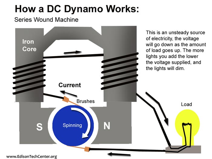
Generators
A mechanical power source is required, such as a turbine powered by falling water, a wind turbine, a gas turbine, or a steam turbine. A shaft from one of these devices is connected to a generator to produce power. Dynamos...
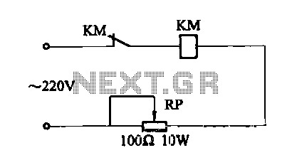
One circuit electromagnetic vibration table
An electromagnetic vibration table or feeder is designed to move small objects along a specific track or cylindrical path through forced vibrations. This device can be custom-built to facilitate the movement of items along a rail tube. The vibration source...
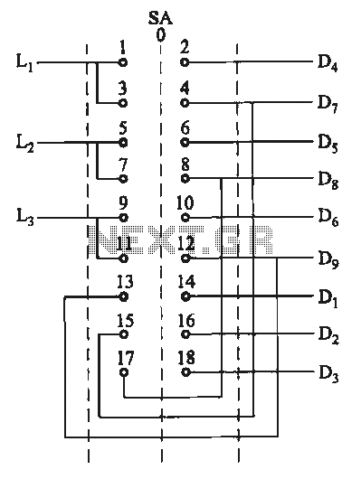
Switching two-speed motor control circuit
The motor switch control circuit depicted in the figure provides two speed settings for counter-steering, allowing for operation at two speeds in opposite directions.
The motor switch control circuit is designed to facilitate the operation of a motor at two distinct...
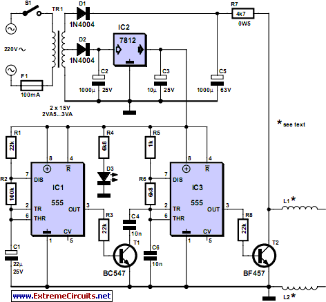
pipe descaler schematics
For many years, magnetic (or electromagnetic) water descaler devices have appeared on the shelves of home improvement and DIY stores across Europe. Despite numerous studies conducted by manufacturers and various consumer associations, none have definitively concluded on the effectiveness of...
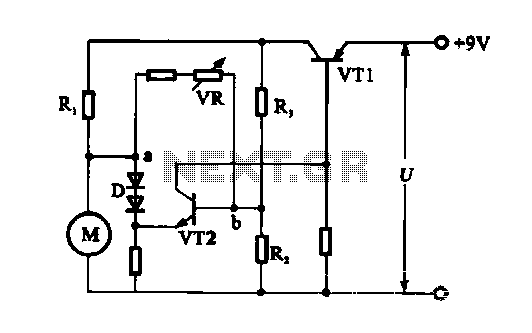
Electronic circuit steady speed motor application
The electronic circuit for steady speed motor applications utilizes an automatic remote control system to regulate the motor power supply, thereby achieving consistent speed control. The circuit diagram illustrates a DC motor connected to the system. Given that the DC...
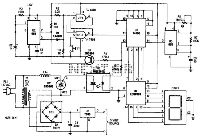
Electromagnetic Ring Launcher Circuit
The electromagnetic ring launcher consists of four subcircuits: a clock circuit utilizing U5, a 555 oscillator/timer configured for astable operation; a countdown/display circuit incorporating U3, a 74190 synchronous up/down counter with BCD outputs set for countdown operation; U4, an ECG8368...
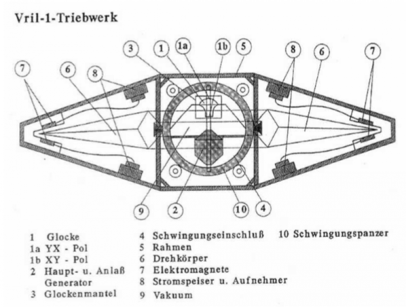
Some Thoughts on Nazi Disc Shaped Flying Machines
There are two methods to counteract the effects of gravity using electromagnetic forces:
1. The first method involves a rotating magnetic field combined with a radial current flow. The resulting force is directed according to the vector cross product of...
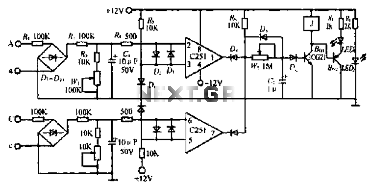
A small generator and network control circuit
Circle i represents a two-phase grid connection line for an AC technology turbine shed, which consists of two lines. A voltage is generated between Ri through a Buck converter, with components R1 and R3 dividing the output. The sampled level...
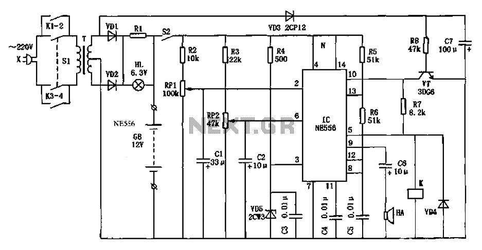
Automatic generator start battery monitor circuit diagram
As shown in the generator start battery automatic monitor circuit diagram.
The generator start battery automatic monitor circuit is designed to oversee the battery's status during generator operation. This circuit ensures that the battery remains charged and functional, preventing premature failure...