


A water tank automatic control circuit
#water tank
#automatic control
#555 timer
#power supply
#rectifier
#filter
#voltage regulation
#sensor
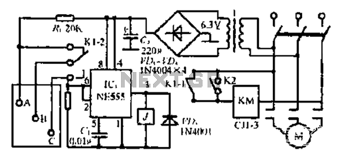
Description: After the 3.40V power supply, the voltage is reduced to 6.3V through a full transition rectification using VDi and V sulfone. The C1 filter provides voltage stabilization after the caution circuit operates at the NE555 voltage level. When the circuit operates under military drawdown conditions, the output at pin 2 of the NE555 shows a low position. This activates an internal circuit that triggers a rotary semi-relay action at pin 3, which in turn activates a dual touch relay, K1-1, to start the pumping motor while K1-2 is closed. Wiring at point C is shorted; when the water level rises to point A by one inch, the power supply voltage increases across resistor R. The voltage at pin 6 of the NE555 is elevated, which triggers the circuit when it reaches 2/3 of VDD. This causes the output at pin 3 to go low, releasing K1-1 and K1-2, thereby stopping the motor operation. The BG connection contacts short-circuit, and the system remains in a standby state until the water level drops below point A and point B. The toggle button K2 is used to manually activate the water gate for exploration purposes.
The circuit utilizes a NE555 timer IC configured in a monostable mode to control the operation of a pumping system based on water level detection. The initial voltage reduction from 3.40V to 6.3V is crucial for the proper functioning of the NE555, as it operates effectively within this voltage range. The C1 capacitor acts as a filter, smoothing out any voltage fluctuations that may occur during operation, ensuring stable performance of the caution circuit.
In this setup, the water level is monitored by a sensor connected to points A and B. When the water level rises to point A, the voltage across resistor R increases, which is sensed by pin 6 of the NE555 timer. Once this voltage reaches 2/3 of the supply voltage (VDD), the output at pin 3 transitions to a low state. This action deactivates the relays K1-1 and K1-2, thus stopping the motor and preventing overflow.
The dual relay configuration allows for redundancy and safety in the pumping operation. The K1-1 relay is responsible for starting the pump, while K1-2 serves as a safety mechanism to ensure the pump does not operate under certain conditions. The shorting of wiring at point C ensures that the system can quickly respond to changes in water levels, maintaining efficient operation.
The toggle button K2 provides manual control over the water gate, allowing for intervention when necessary, such as during maintenance or exploration. The design emphasizes reliability and responsiveness, making it suitable for various applications where water level management is critical.After 3t40V power Sutra T seats is reduced to 6.3V low voltage by VDi - V sulfone full transition rectified. c1 filter provide after - when caution circuit NI/555 operating vol tage: NE555 (2) llt when canthus under military drawdown point B; 0 showed a low position, Chong Mi touch internal circuit overturns, Rotary (3) pin output high power semi-relay action was electric, dual touch n - K1 -l closed Yu pumping motor is activated while closing Kl 2 B. Point C are shorted wiring: When the water level rose to the point A t i inch, the power supply voltage over R.
Tan. Office points to NE555 (2), (6) feet away from the potential promoted to potential. (6) feet too trigger-based circuit provider side, when the voltage reaches 2/3VDD lq born of the circuit that is pulled over so (3) pin output goes low, J first electric release Kl - I, Kl -2, the motor stops JL work. BG connection contacts jump AB heap line is short-circuited. fb-like nervous waiting to enter the road. Live below the water level is higher than the Dong A point B point. Toggle buttons K2 Oh boom in exploration will draw water gate.
The circuit utilizes a NE555 timer IC configured in a monostable mode to control the operation of a pumping system based on water level detection. The initial voltage reduction from 3.40V to 6.3V is crucial for the proper functioning of the NE555, as it operates effectively within this voltage range. The C1 capacitor acts as a filter, smoothing out any voltage fluctuations that may occur during operation, ensuring stable performance of the caution circuit.
In this setup, the water level is monitored by a sensor connected to points A and B. When the water level rises to point A, the voltage across resistor R increases, which is sensed by pin 6 of the NE555 timer. Once this voltage reaches 2/3 of the supply voltage (VDD), the output at pin 3 transitions to a low state. This action deactivates the relays K1-1 and K1-2, thus stopping the motor and preventing overflow.
The dual relay configuration allows for redundancy and safety in the pumping operation. The K1-1 relay is responsible for starting the pump, while K1-2 serves as a safety mechanism to ensure the pump does not operate under certain conditions. The shorting of wiring at point C ensures that the system can quickly respond to changes in water levels, maintaining efficient operation.
The toggle button K2 provides manual control over the water gate, allowing for intervention when necessary, such as during maintenance or exploration. The design emphasizes reliability and responsiveness, making it suitable for various applications where water level management is critical.After 3t40V power Sutra T seats is reduced to 6.3V low voltage by VDi - V sulfone full transition rectified. c1 filter provide after - when caution circuit NI/555 operating vol tage: NE555 (2) llt when canthus under military drawdown point B; 0 showed a low position, Chong Mi touch internal circuit overturns, Rotary (3) pin output high power semi-relay action was electric, dual touch n - K1 -l closed Yu pumping motor is activated while closing Kl 2 B. Point C are shorted wiring: When the water level rose to the point A t i inch, the power supply voltage over R.
Tan. Office points to NE555 (2), (6) feet away from the potential promoted to potential. (6) feet too trigger-based circuit provider side, when the voltage reaches 2/3VDD lq born of the circuit that is pulled over so (3) pin output goes low, J first electric release Kl - I, Kl -2, the motor stops JL work. BG connection contacts jump AB heap line is short-circuited. fb-like nervous waiting to enter the road. Live below the water level is higher than the Dong A point B point. Toggle buttons K2 Oh boom in exploration will draw water gate.
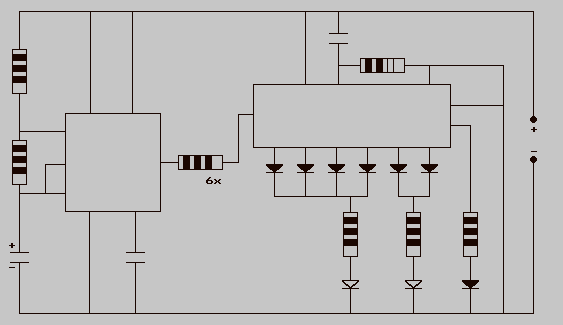
Traffic Lights-LEDS
The 555 timer IC is connected for Astable Operation, the clock pulses are fed to the 4017 IC via the 10K resistor. The 4017 is a 10 stage counter, therefore the sequence of the traffic lights is spread over 10...
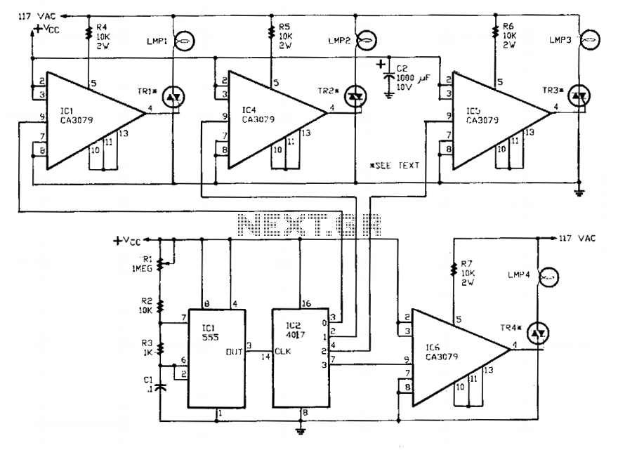
Sequential flasher
A 555 timer, referred to as IC1, controls a 4017 CMOS decade counter. The first four outputs of the 4017 drive a CA3079 zero-voltage switch. Pin 9 of the CA3079 is utilized to inhibit output from pin 4, which disables...

new pedal schematic
U1 (555 in monostable mode) generates a square wave signal that corresponds to the input signal. This square wave is then sent to the mixer (U2) along with the original signal for mixing, effectively functioning as a frequency doubler. Each...
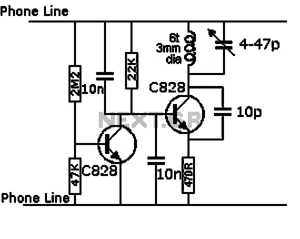
astable circuit produce pulses
This circuit was first introduced by Signetics Corporation as the SE555/NE555 around 1971. Pin connections and functions are as follows: Pin 1 (Ground) is the most negative supply potential of the device, typically connected to circuit common when powered by...
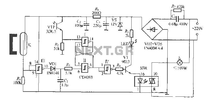
Gate automatic lamp circuit
The circuit utilizes multiple integrated circuits to form an automatic lighting device that is activated by door and window sensors. It includes CD4093 digital integrated circuits, a relay, and a power supply circuit. The system typically remains closed when a...
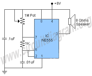
555 tone generator
This is a 555 tone generator circuit based on the NE555 timer IC. The NE555 is a well-known integrated circuit utilized in various applications and performs a multitude of functions. In this circuit, the IC operates as an astable oscillator,...
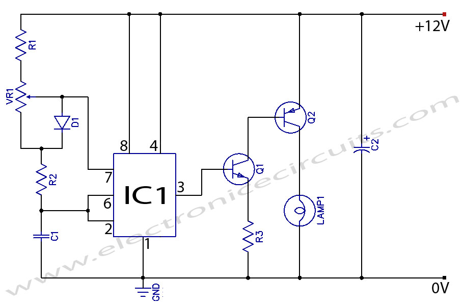
12V DC Light Dimmer Circuit Using 555 Timer IC
When the potentiometer is in the upper position, the capacitor charges rapidly through both 1k resistors and the diode, resulting in a brief positive interval and an extended negative interval, which dims the lamp to near darkness. Conversely, when the...
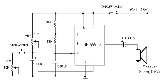
Electronic Siren
This circuit produces a sound similar to a factory siren. It makes use of a 555 timer IC used as an astable multivibrator of a center frequency of about 300Hz. The frequency is controlled by pin 5 of the IC....
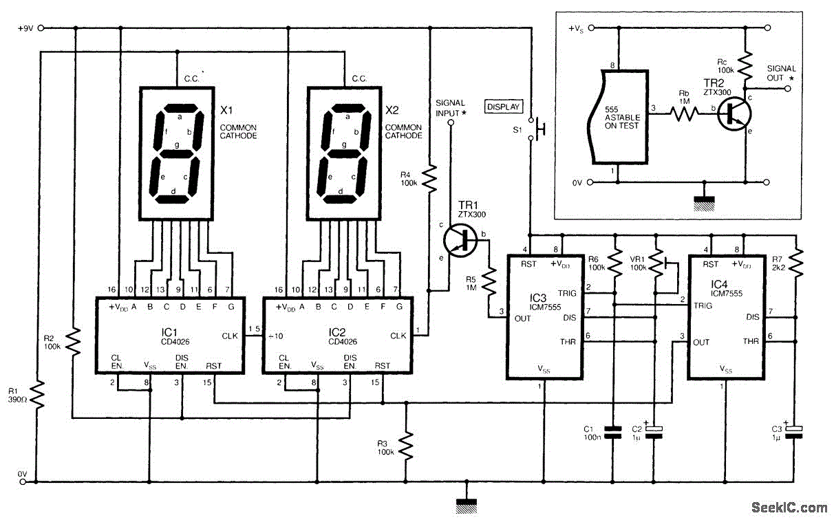
555 ASTABLE_FREQUENCY METER
The circuit illustrated is a straightforward digital frequency meter that displays the frequency in hertz of an astable 555 timer. It may potentially be modified for alternative applications. An NPN transistor, TR2, is linked to the 555 astable timer being...