


Amproluck W850ES microwave auto-sensing electronic microwave circuit diagram
#microwave
#sensor
#thermal sensor
#relay
#transformer
#motor control
#high voltage
#temperature control
#home appliance
#automation
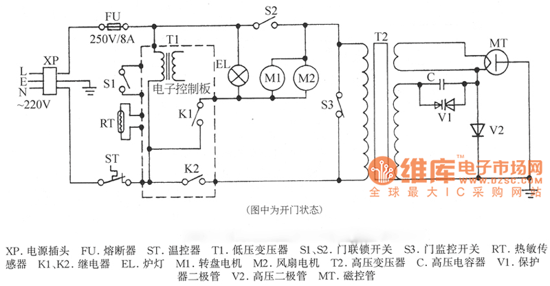
Description: XP power plug, FU fuse, ST temperature control, T1 low-voltage transformers, S1, S2 door interlock switch, S3 threshold control switch, RT thermal sensor, K1, K2 relay, EL furnace light, M1 wheel motor, M2 fan motor, T2 high-voltage transformer, C high voltage capacitor, V1 protection diode, V2 high voltage diode, MT magnetron.
The described circuit comprises several essential components that work together to ensure safe and efficient operation of a heating system, likely for an industrial application.
The XP power plug serves as the primary power input, delivering electrical energy to the circuit. The FU fuse is included for overcurrent protection, preventing damage to the circuit in case of a fault. The ST temperature control regulates the operating temperature of the system, ensuring it remains within safe limits.
Low-voltage transformers (T1) convert the mains voltage to a lower level suitable for use by other components. The door interlock switches (S1, S2) ensure that the system cannot operate unless the doors are securely closed, enhancing safety. The S3 threshold control switch may be used to set operational limits for the system, triggering different actions based on temperature or other parameters.
The RT thermal sensor monitors temperature and provides feedback to the control system, allowing for adjustments based on real-time conditions. The K1 and K2 relays act as switching elements that control the power to various components based on signals received from the control logic.
The EL furnace light indicates when the system is operational, providing visual feedback to the user. The M1 wheel motor and M2 fan motor are responsible for mechanical movement and airflow, respectively, essential for maintaining efficient heating and cooling cycles.
The high-voltage transformer (T2) steps up the voltage for the magnetron (MT), which generates microwave energy for heating applications. The high voltage capacitor (C) stores electrical energy for discharge, supporting the operation of the magnetron. Protection is provided by the V1 protection diode and the V2 high voltage diode, which safeguard the circuit from voltage spikes and ensure proper current flow.
This schematic illustrates a comprehensive design that integrates safety features, temperature control, and efficient power management, making it suitable for various heating applications.XP-power plug, FU-fuse, ST-temperature control, T1-low-voltage transformers, S1, S2-door interlock switch, S3-threshold control switch, RT-thermal sensor, K1, K2-relay, EL- furnace light, M1-wheel motor, M2-fan motor, T2-high-voltage transformer, C-high voltage capacitor, V1-protection diode, V2-high voltage diode, MT-magnetron..
The described circuit comprises several essential components that work together to ensure safe and efficient operation of a heating system, likely for an industrial application.
The XP power plug serves as the primary power input, delivering electrical energy to the circuit. The FU fuse is included for overcurrent protection, preventing damage to the circuit in case of a fault. The ST temperature control regulates the operating temperature of the system, ensuring it remains within safe limits.
Low-voltage transformers (T1) convert the mains voltage to a lower level suitable for use by other components. The door interlock switches (S1, S2) ensure that the system cannot operate unless the doors are securely closed, enhancing safety. The S3 threshold control switch may be used to set operational limits for the system, triggering different actions based on temperature or other parameters.
The RT thermal sensor monitors temperature and provides feedback to the control system, allowing for adjustments based on real-time conditions. The K1 and K2 relays act as switching elements that control the power to various components based on signals received from the control logic.
The EL furnace light indicates when the system is operational, providing visual feedback to the user. The M1 wheel motor and M2 fan motor are responsible for mechanical movement and airflow, respectively, essential for maintaining efficient heating and cooling cycles.
The high-voltage transformer (T2) steps up the voltage for the magnetron (MT), which generates microwave energy for heating applications. The high voltage capacitor (C) stores electrical energy for discharge, supporting the operation of the magnetron. Protection is provided by the V1 protection diode and the V2 high voltage diode, which safeguard the circuit from voltage spikes and ensure proper current flow.
This schematic illustrates a comprehensive design that integrates safety features, temperature control, and efficient power management, making it suitable for various heating applications.XP-power plug, FU-fuse, ST-temperature control, T1-low-voltage transformers, S1, S2-door interlock switch, S3-threshold control switch, RT-thermal sensor, K1, K2-relay, EL- furnace light, M1-wheel motor, M2-fan motor, T2-high-voltage transformer, C-high voltage capacitor, V1-protection diode, V2-high voltage diode, MT-magnetron..
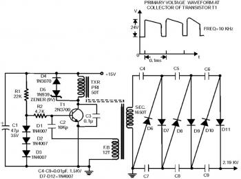
2000v high voltage low current power
A high voltage power supply can be a beneficial source that can be utilized in various applications such as biasing gas-discharge tubes and radiation detectors. This power supply can also be employed for property protection through the electric charging of...
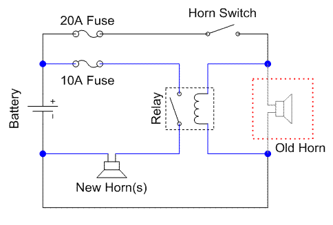
GS500 Horn
A relay is an electrically operated switch that utilizes a coil to create magnetism, which closes the contacts of the switch. In automotive applications, a 12V signal through the coil allows 12V to flow through the switch contacts. The advantage...
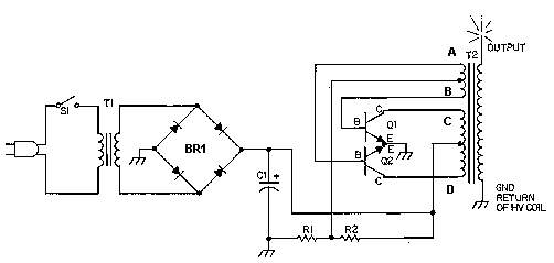
Solid State Tesla Coil/High Voltage Generator Circuit
This circuit is designed to demonstrate high frequency and high voltage, capable of producing up to approximately 30 kV, depending on the transformer utilized. It is an economical and straightforward project, primarily using a standard TV flyback transformer. The circuit...
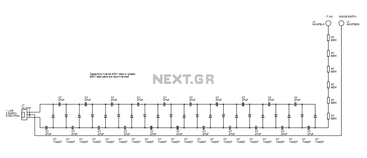
Air Ioniser circuit
A basic mains driven Cockroft ladder high voltage generator is shown in the schematic. This is functionally the same as a project in Electronics Today International many years ago. The peak mains voltage of 340V appears across each capacitor and...
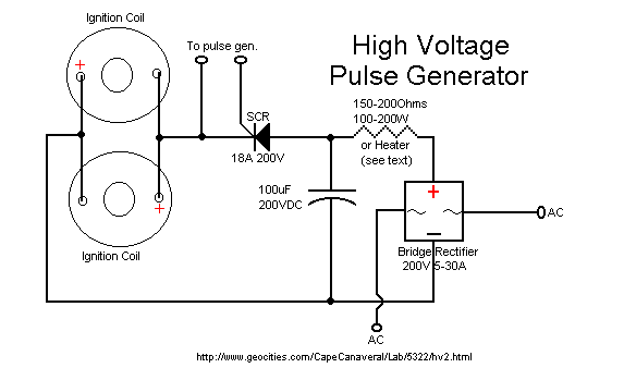
60kv ignition coil driver circuit
The ignition coil driver circuit described is a highly regarded design, reportedly created by Jochen Kronjaeger. It is intended to operate from a 230V source, although a modified version can function effectively at 120V. The circuit requires two ignition coils...
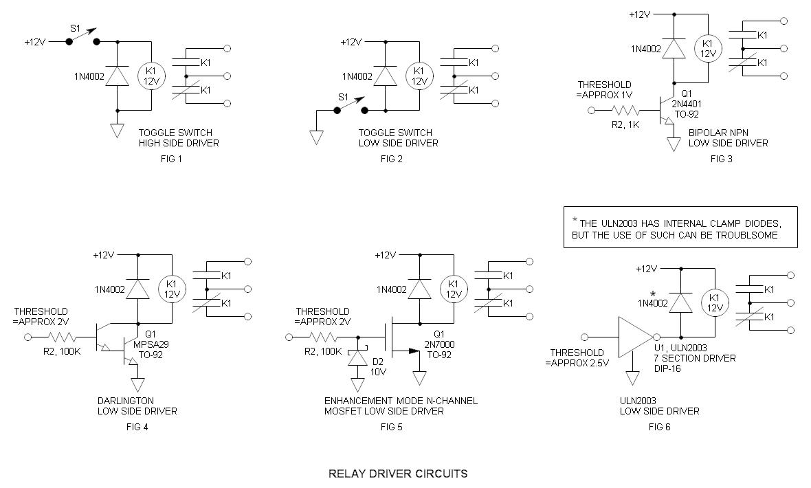
Relay Driver
Relays have been in use for a considerable duration. Although they are frequently substituted with solid-state switches, relays possess distinct characteristics that render them more robust.
Relays are electromechanical devices that utilize an electromagnetic coil to mechanically operate a switch. The...
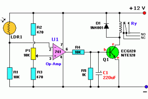
switch with relay schematic
The Light Switch with Relay is a series of electronic switches that are controlled by light intensity. This circuit can automatically control lighting, turning the lights on when ambient light levels decrease. The threshold for light activation in the Light...
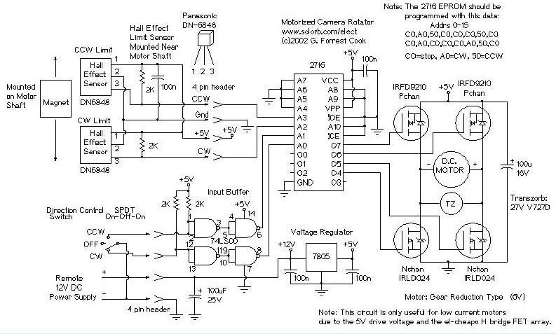
Motorized Video Camera Mount
The camera rotator circuit utilizes a 2716 EPROM to store a logic value table that governs the motor driver (H-bridge) circuit. The schematic illustrates the EPROM data. By employing the EPROM, a significant number of discrete gates are eliminated. The...
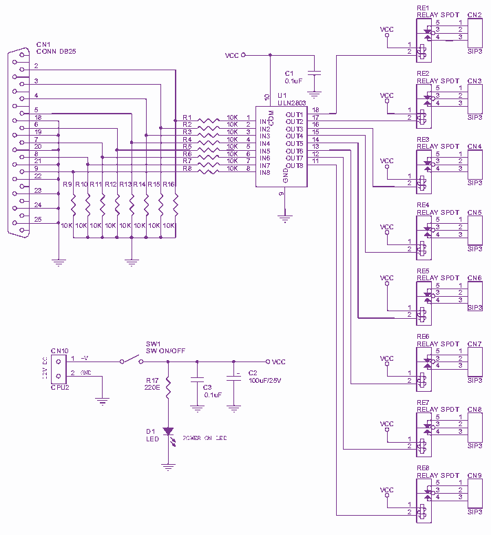
8 Channel LPT relay board
Channel Relay Board is a simple and convenient way to interface 8 relays for switching application in your project. Input - 12 VDC @ 336 mA. Output - eight SPDT relay. Relay specification - 5 A @ 230 VAC. Trigger...