


automatic water tank filler circuit diagram
#water level sensor
#automation
#pump control
#farm equipment
#water management
#timer
#sensor circuit
#livestock care
#irrigation
#header tank
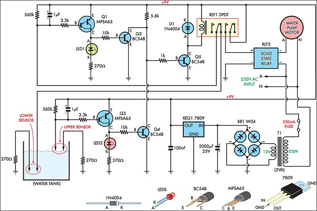
Description: This circuit is designed to fill a header tank for a reticulated water supply on a farm. It serves eight troughs located in different paddocks, where a lack of water could have serious consequences for livestock. Previously, the tank was filled daily using a time clock, which proved ineffective. During hot weather, the livestock would deplete the tank's water supply regularly, leaving them without water for several hours. Conversely, during wet weather, the tank would overflow if the cattle did not consume much water. The described circuit maintains the water level in the header tank within specified limits. It controls a 3HP submersible bore pump that requires a solid-state relay capable of handling the high starting current. Two Darlington transistors, Q1 and Q3, are used in conjunction with Q2 and Q4, which are connected to the upper and lower water sensors in the tank. Q2 and Q4 share a common 5.6 kΩ load resistor and function as a NOR gate. The output of the NOR gate drives Q5, activating relay RLY1. When the water level is low, both sensors are open-circuit, resulting in a high output from the NOR gate, which turns on the relay. This action opens the normally closed (NC) contacts of the relay, disconnecting the lower sensor. The upper sensor remains open-circuit, keeping the NOR gate output high and the relay activated. The normally open (NO) contact of the relay closes to operate the solid-state relay RLY2, activating the pump. This condition persists until the water reaches the upper sensor, which causes the NOR gate output to drop to 0V, disabling relay RLY1 and stopping the pump. In practice, the upper level sensor is positioned just below the overflow level of the tank, while the lower sensor is located about halfway up the tank. The sensor contacts consist of two stainless steel screws placed approximately 25 mm apart and secured through the poly tank walls. The wiring junctions on the tank's side are protected using neutral-cure silicone sealant.
The electronic schematic for this water level control circuit incorporates several key components and configurations to ensure reliable operation. The two water level sensors, typically constructed from stainless steel screws, serve as conductive probes that detect the presence or absence of water. These sensors are strategically positioned within the tank to define the upper and lower water levels. The lower sensor activates the pump when the water level drops below a certain threshold, while the upper sensor deactivates the pump once the water level reaches the desired maximum.
The use of Darlington transistors Q1, Q2, Q3, and Q4 enhances the circuit's ability to amplify the signals from the water sensors, enabling the NOR gate to produce a consistent output. The NOR gate configuration is crucial, as it ensures that the relay remains activated only when both sensors are not submerged, thereby preventing unintended activation of the pump.
Relay RLY1 controls the power supply to the pump, while solid-state relay RLY2 manages the high starting current required by the 3HP submersible bore pump. This arrangement allows for efficient control of the pump's operation without risking damage to the components due to excessive current.
The entire circuit is designed to operate within the harsh environmental conditions typically found on a farm, with the use of silicone sealant providing protection against moisture and corrosion at the wiring junctions. This design ensures that the livestock always have access to water, mitigating the risks associated with dehydration or flooding, thereby enhancing farm productivity and animal welfare.This circuit has been very useful in filling a header tank for a reticulated water supply on a farm. Eight troughs are supplied in different paddocks where a lack of water would have serious consequences for the stock. In the past, the tank had been filled daily by a time clock which was not successful. During hot weather, the stock would empty th e tank on a regular basis and then be without water for several hours or the tank would overflow and flood the area if the weather was wet and the cattle did not drink much. The circuit described has been used to maintain the level of water in the header tank within prescribed limits.
It controls a 3HP submersible bore pump which has a high starting current, necessitating a solid-state relay sufficient to take the starting load. Two Darlington transistors, Q1 & Q3, in conjunction with Q2 & Q4, are connected to the upper and lower water sensors in the tank.
Q2 & Q4 have a common 5. 6kO load resistor and function as a NOR gate. The output of the NOR gate drives Q5 which activates relay RLY1. Initially, when the water level is low, both sensors will be open-circuit, the NOR gate output will be high and the relay will be turned on. This causes the normally closed (NC) contacts of the relay to open and disconnect the lower sensor. However, the upper sensor will still be open circuit and the NOR gate output will be high, keeping the relay closed.
The normally open (NO) contact of the relay will be closed to operate the solid-state relay RLY2 to run the pump. This state continues until the water reaches the top sensor which will then drop the output from the NOR gate to 0V.
The disables relay RLY1 and the pump is stopped. In practice the upper level sensor is just below the overflow from the tank and the lower sensor about half way up the tank. The sensor contacts are simply two stainless steel screws about 25mm apart and screwed through the poly tank walls.
The wiring junctions on the side of the tank are protected by neutral-cure silicone sealant.
The electronic schematic for this water level control circuit incorporates several key components and configurations to ensure reliable operation. The two water level sensors, typically constructed from stainless steel screws, serve as conductive probes that detect the presence or absence of water. These sensors are strategically positioned within the tank to define the upper and lower water levels. The lower sensor activates the pump when the water level drops below a certain threshold, while the upper sensor deactivates the pump once the water level reaches the desired maximum.
The use of Darlington transistors Q1, Q2, Q3, and Q4 enhances the circuit's ability to amplify the signals from the water sensors, enabling the NOR gate to produce a consistent output. The NOR gate configuration is crucial, as it ensures that the relay remains activated only when both sensors are not submerged, thereby preventing unintended activation of the pump.
Relay RLY1 controls the power supply to the pump, while solid-state relay RLY2 manages the high starting current required by the 3HP submersible bore pump. This arrangement allows for efficient control of the pump's operation without risking damage to the components due to excessive current.
The entire circuit is designed to operate within the harsh environmental conditions typically found on a farm, with the use of silicone sealant providing protection against moisture and corrosion at the wiring junctions. This design ensures that the livestock always have access to water, mitigating the risks associated with dehydration or flooding, thereby enhancing farm productivity and animal welfare.This circuit has been very useful in filling a header tank for a reticulated water supply on a farm. Eight troughs are supplied in different paddocks where a lack of water would have serious consequences for the stock. In the past, the tank had been filled daily by a time clock which was not successful. During hot weather, the stock would empty th e tank on a regular basis and then be without water for several hours or the tank would overflow and flood the area if the weather was wet and the cattle did not drink much. The circuit described has been used to maintain the level of water in the header tank within prescribed limits.
It controls a 3HP submersible bore pump which has a high starting current, necessitating a solid-state relay sufficient to take the starting load. Two Darlington transistors, Q1 & Q3, in conjunction with Q2 & Q4, are connected to the upper and lower water sensors in the tank.
Q2 & Q4 have a common 5. 6kO load resistor and function as a NOR gate. The output of the NOR gate drives Q5 which activates relay RLY1. Initially, when the water level is low, both sensors will be open-circuit, the NOR gate output will be high and the relay will be turned on. This causes the normally closed (NC) contacts of the relay to open and disconnect the lower sensor. However, the upper sensor will still be open circuit and the NOR gate output will be high, keeping the relay closed.
The normally open (NO) contact of the relay will be closed to operate the solid-state relay RLY2 to run the pump. This state continues until the water reaches the top sensor which will then drop the output from the NOR gate to 0V.
The disables relay RLY1 and the pump is stopped. In practice the upper level sensor is just below the overflow from the tank and the lower sensor about half way up the tank. The sensor contacts are simply two stainless steel screws about 25mm apart and screwed through the poly tank walls.
The wiring junctions on the side of the tank are protected by neutral-cure silicone sealant.
A Regularly Repeating Interval Timer
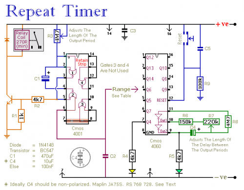
This circuit features an adjustable output timer capable of re-triggering at regular intervals. The output duration can range from a fraction of a second to half an hour or longer, with the ability to recur at intervals spanning from seconds...
Time Switch
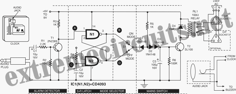
This circuit is specifically designed for individuals who frequently need to wake up early in the morning. Standard alarms in electronic watches are often insufficiently loud.
The circuit utilizes a high-decibel audio output mechanism to ensure that the alarm is audible...
Automatic Water Tank Filler Circuit
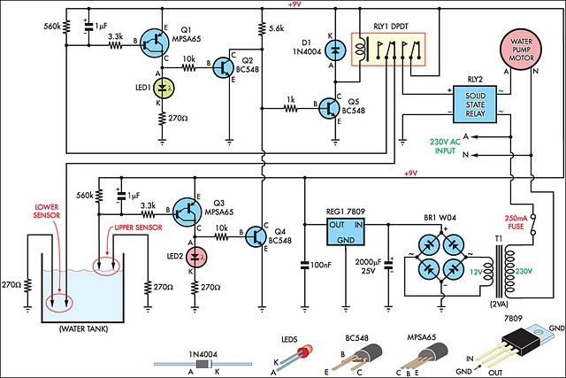
This circuit is designed to effectively fill a header tank for a reticulated water supply on a farm. It supports eight troughs located in various paddocks, where inadequate water supply can have serious repercussions for livestock. Previously, a timer-based system...
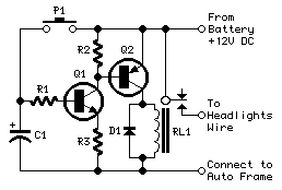
Headlights Timer
This device is a simple timer, allowing to keep on the headlights of your vehicle for about 1min. and 30sec., e.g. when accessing some dark place, without the necessity of coming back to switch-off the lights.
The circuit design for this...
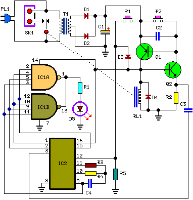
A Bedside Lamp Timer Circuit Schematic
The purpose of this circuit is to power a lamp or other appliance for a specified duration (30 minutes in this case) and then automatically turn it off. This functionality is particularly useful for reading in bed at night, as...
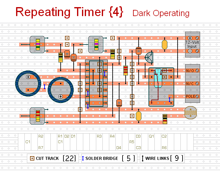
repeating timer no4
This circuit functions as the inverse of Repeating Timer No. 3. Its operation is constrained to the hours of darkness. The variable resistor (preset) allows for the selection of the darkness level at which the timer will activate.
The circuit is...
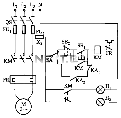
Control circuit of automatic water
In certain locations near the reservoir or well, when the water level is constrained by the water towers, there is a need for simultaneous monitoring of the water towers and reservoirs as part of an automatic water control system. This...
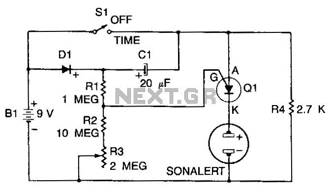
Three-minute-timer
When S1 is off, C1 charges to within 0.5 V of the battery voltage through diode D1 and resistor R4. When S1 is closed, the anode of the PUT rises to the positive supply voltage. The PUT does not conduct...
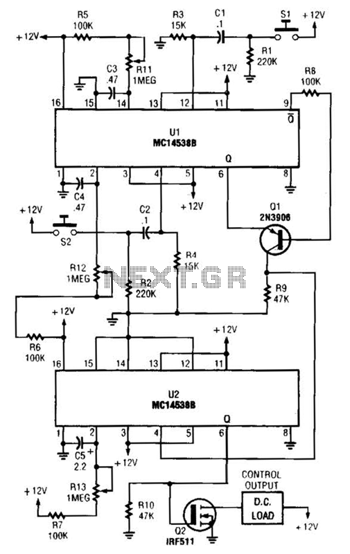
Timed Safety Circuit Circuit
When switch SI is closed, pin 9 of operational amplifier U1 goes low, activating transistor Q1 for a predetermined duration. If switch S2 is closed during this time, transistor Q2 is activated for another predetermined duration. Resistors R1 and R13...