


Door Chime with ATtiny12
#door chime
#ATtiny12
#LED indicator
#timer circuit
#pushbutton
#toggle switch
#home automation
#doorbell control
#18 VAC
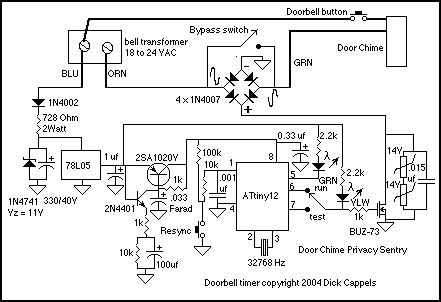
Description: The device described here does just that. The circuit connects to the doorbell circuit, taking power from the 18 VAC from the doorbell transformer and switching power to the doorbell circuit most of the day. The user interface is a pushbutton, a toggle switch, and two LEDs. One LED, the green one, blinks at 1 Hz, just to give some comfort that the circuit is working. The amber LED glows whenever the doorbell is disabled. To set the timer, the user pushes the button momentarily, and when it is released, the amber LED will come on and the doorbell circuit is disabled (the doorbell button doesn't work) for a 10-hour period. At the end of the 10-hour period, the amber LED goes off and the doorbell is enabled. More: 24 hours after the button was last pushed, the amber LED comes back on and the door chime circuit is disabled again. This cycle repeats every 24 hours, and because its timing is set by a crystal oscillator, it should be able to go for months or years without needing to be reset. The circuit consists of a power supply, a capacitor backup circuit, an Atmel ATtiny12 microcontroller as a timer, and a solid-state relay circuit to switch the AC voltage in the doorbell circuit. The simple user interface is comprised of a resync button to synchronize the timer, a bypass switch to bypass the timer if desired, and two status indicator LEDs. It is designed to be used by people who are not technically inclined. The bell transformer, the doorbell button, and the doorbell are not in the enclosure; they are built into the house. The bypass switch and resync (or reset) button are mounted on the enclosure. Power for the circuit is derived from a half-wave rectifier. One end of the bell transformer (the one with the orange wire, marked "ORN" connected to it) connects to circuit common each half cycle through one of the diodes in the diode bridge. During the same half cycle, the 1N4002 conducts, charging the 330 µF capacitor up to a maximum of 11 volts. The filtered voltage powers the 78L05 5-volt regulator. The current is limited with the 728 Ohm dropping resistor to a maximum of 30 milliamps in order to minimize the maximum load on the bell transformer and to limit the amount of power that could be dissipated by any component on the board in the event of a component failure. The use of eight 1/4 watt resistors connected in series provides additional safety compared to using a single 750 Ohm 2 Watt resistor, as the power dissipated will be spread over a larger area of the phenolic circuit board. As a rule, resistors are not used beyond 50% of their rated power; in this case, the resistor string operates at 35% of rated power. A 0.033 farad capacitor is connected to the 2SA1020Y and the 2N4401 to provide backup power to keep the timer running in the event of a power failure. The 2N4401 connects the output of the 5-volt regulator to the ATtiny12 microcontroller when AC voltage is present and disconnects the controller's power supply from the LEDs when AC voltage is not present. This disconnection prevents the LEDs from discharging the 0.033 farad capacitor. The 2N4401 turns on the 2SA1020Y when power is first applied to the circuit, then quickly disconnects itself when the +5 volts starts to dip. The 0.033 farad capacitor supplies voltage to the ATtiny12 through a 1k resistor. An alternative, the 2N2907, can be used in place of the 2SA1020Y.The device described here does just that. The circuit connects to the doorbell circuit - taking power from the 18 VAC from the doorbell transformer and switching power to the doorbell circuit most of the day. The user interface is a pushbutton, a toggle switch, and two LEDs. One LED - the green one -blinks at 1 Hz, just to give me some comfort that the circuit is working. The amber LED glows whenever the doorbell is disabled. To set the timer, you just push the button momentarily, and when its released, the amber LED will come on and the doorbell circuit is disabled (the door bell button doesn't work) for a 10 hour period.
At the end of the 10 hour period, the amber LED goes off and the doorbell is enabled. 24 Hours after the button was last pushed, the amber LED comes back on and the door chime circuit is disabled again. this cycle repeats every 24 hours, and because its timing is set by a crystal oscillator, it should be able to go for months or years without needing to be reset.
The circuit consists of a power supply, a capacitor back-up circuit, a Atmel ATtiny12 microcontroller as a timer, and solid state realy circuit to switch the AC voltage in the doorbell circuit. The simple user interface is comprised of a resync button to synchronize the timer, a bypass switch to bypass the timer if desired, and two status indicator LEDs.
It is designed to be used by people who are not technically inclined. The bell transformer, the doorbell button, and the doorbell are not in the enclosure - they are built into the house. The bypass switch and resync (or reset) button are mounted on the enclosure. Power for the circuit is derived from a half wave rectifier. One end of the bell transformer (the one with the orange wire, marked "ORN" connected to it) connects to circuit common each half cycle through one of the diodes in the diode bridge.
During the same half cycle, the 1N4002 conducts, charging the 330 uf capacitor up to a maximum of 11 volts. The filtered voltage powers the 78L05 5 volt regulator. The current is limited with the 728 Ohm dropping resistor to a maximum of 30 milliamps in order to minimize the maximum load on the bell transformer, and to limit the amount of power that could be dissipated by any component on the board in the event of a component failure.
The use of eight 1/4 watt resistors connected in series makes me feel a little more comfortable than using a single 750 Ohm 2 Watt resistor since the power dissipated will be spread over a large area of the phenolic circuit -pheonlic tends to discolor from heat more easily than fiberglass board, and even if a few of the resistors shorted, the others would be able to handle the increased dissipation -giving a little extra safety. As a rule, I don't use resistors beyond 50% of their rated power. In this case, the resistor string runs at 35% of rated power. A .033 farad (not microfarad) capacitor is connected to the 2SA1020Y and the 2N4401 to provide backup power to keep the timer running in the event of a power failure.
The 2N4401 is there to connect the output of the 5 volt regulator to the ATtiny12 microcontroller when AC voltage is present, and more importantly, to disconnect the controller's power supply from the LEDs when AC voltage is not present. Disconnecting the ATtiny12 from the LEDs keeps the LEDs from discharging the .033 farad capacitor. The 2N4401 is there to turn on the 2SA1020Y when power is first applied to the circuit, then to quickly disconnect itself from the circuit when the +5 volts starts to dip.
The .033 farad capacitor supplies voltage to the ATtiny12 through the 1k resistor. By the way, you can use an 2N2907 in place of the 2SA1020Y.
At the end of the 10 hour period, the amber LED goes off and the doorbell is enabled. 24 Hours after the button was last pushed, the amber LED comes back on and the door chime circuit is disabled again. this cycle repeats every 24 hours, and because its timing is set by a crystal oscillator, it should be able to go for months or years without needing to be reset.
The circuit consists of a power supply, a capacitor back-up circuit, a Atmel ATtiny12 microcontroller as a timer, and solid state realy circuit to switch the AC voltage in the doorbell circuit. The simple user interface is comprised of a resync button to synchronize the timer, a bypass switch to bypass the timer if desired, and two status indicator LEDs.
It is designed to be used by people who are not technically inclined. The bell transformer, the doorbell button, and the doorbell are not in the enclosure - they are built into the house. The bypass switch and resync (or reset) button are mounted on the enclosure. Power for the circuit is derived from a half wave rectifier. One end of the bell transformer (the one with the orange wire, marked "ORN" connected to it) connects to circuit common each half cycle through one of the diodes in the diode bridge.
During the same half cycle, the 1N4002 conducts, charging the 330 uf capacitor up to a maximum of 11 volts. The filtered voltage powers the 78L05 5 volt regulator. The current is limited with the 728 Ohm dropping resistor to a maximum of 30 milliamps in order to minimize the maximum load on the bell transformer, and to limit the amount of power that could be dissipated by any component on the board in the event of a component failure.
The use of eight 1/4 watt resistors connected in series makes me feel a little more comfortable than using a single 750 Ohm 2 Watt resistor since the power dissipated will be spread over a large area of the phenolic circuit -pheonlic tends to discolor from heat more easily than fiberglass board, and even if a few of the resistors shorted, the others would be able to handle the increased dissipation -giving a little extra safety. As a rule, I don't use resistors beyond 50% of their rated power. In this case, the resistor string runs at 35% of rated power. A .033 farad (not microfarad) capacitor is connected to the 2SA1020Y and the 2N4401 to provide backup power to keep the timer running in the event of a power failure.
The 2N4401 is there to connect the output of the 5 volt regulator to the ATtiny12 microcontroller when AC voltage is present, and more importantly, to disconnect the controller's power supply from the LEDs when AC voltage is not present. Disconnecting the ATtiny12 from the LEDs keeps the LEDs from discharging the .033 farad capacitor. The 2N4401 is there to turn on the 2SA1020Y when power is first applied to the circuit, then to quickly disconnect itself from the circuit when the +5 volts starts to dip.
The .033 farad capacitor supplies voltage to the ATtiny12 through the 1k resistor. By the way, you can use an 2N2907 in place of the 2SA1020Y.
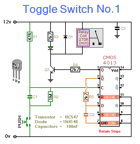
electronic toggle switch no1
This circuit activates and deactivates a relay with the press of a button. Any momentary push-to-make switch can be utilized. Pressing the button once will activate the relay, while pressing it again will deactivate the relay. The circuit is designed...
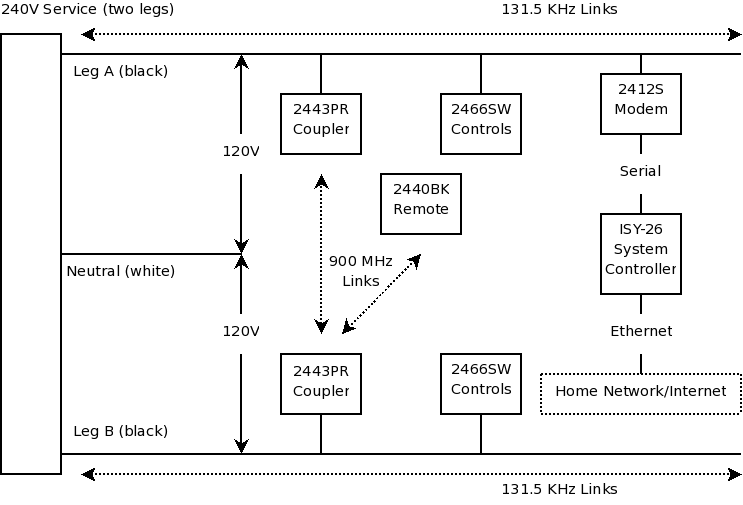
home automation Installation
First and foremost, if one is not skilled with tools and electrical systems, it is advisable to hire a qualified electrician rather than attempting to undertake this task independently. The electrician should review this page for specific cautions and advice....
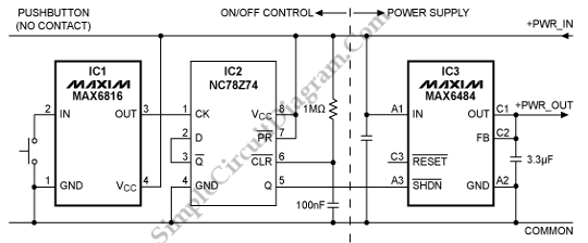
ON/OFF Power Control with Single Pushbutton
Today, simplicity and minimal controls are required for the design of a handheld device. It would be very useful if a circuit allows us to turn the power on or off.
A handheld device requires an efficient power management circuit to...
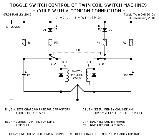
Toggle Switch Control Of Twin Coil Switch Machines
These circuits allow an ON-ON type DPDT toggle switch to control a twin coil switch machine motor. The handle of the switch can then be used to indicate the route selected. The circuits are also able to control LEDs that...
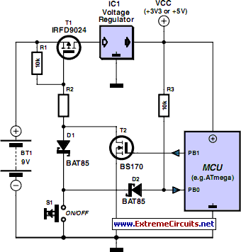
The Gentle Touch
Modern consumer appliances often lack a traditional mains switch. Instead, they are activated and deactivated via a button on a remote control, similar to other functions. This circuit illustrates how a device can be toggled on and off using a...
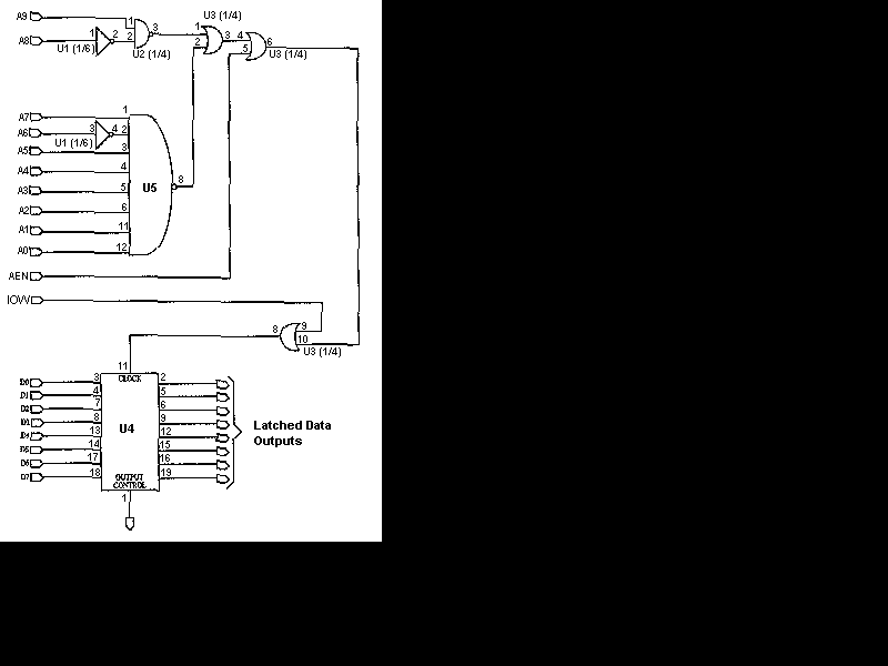
Computerize Your Room/House
You have read about computerized rooms or seen home automation products advertised in electronics magazines. You have decided to try it yourself. However, it is important to note that this project is not inexpensive. A computer is required, which is...
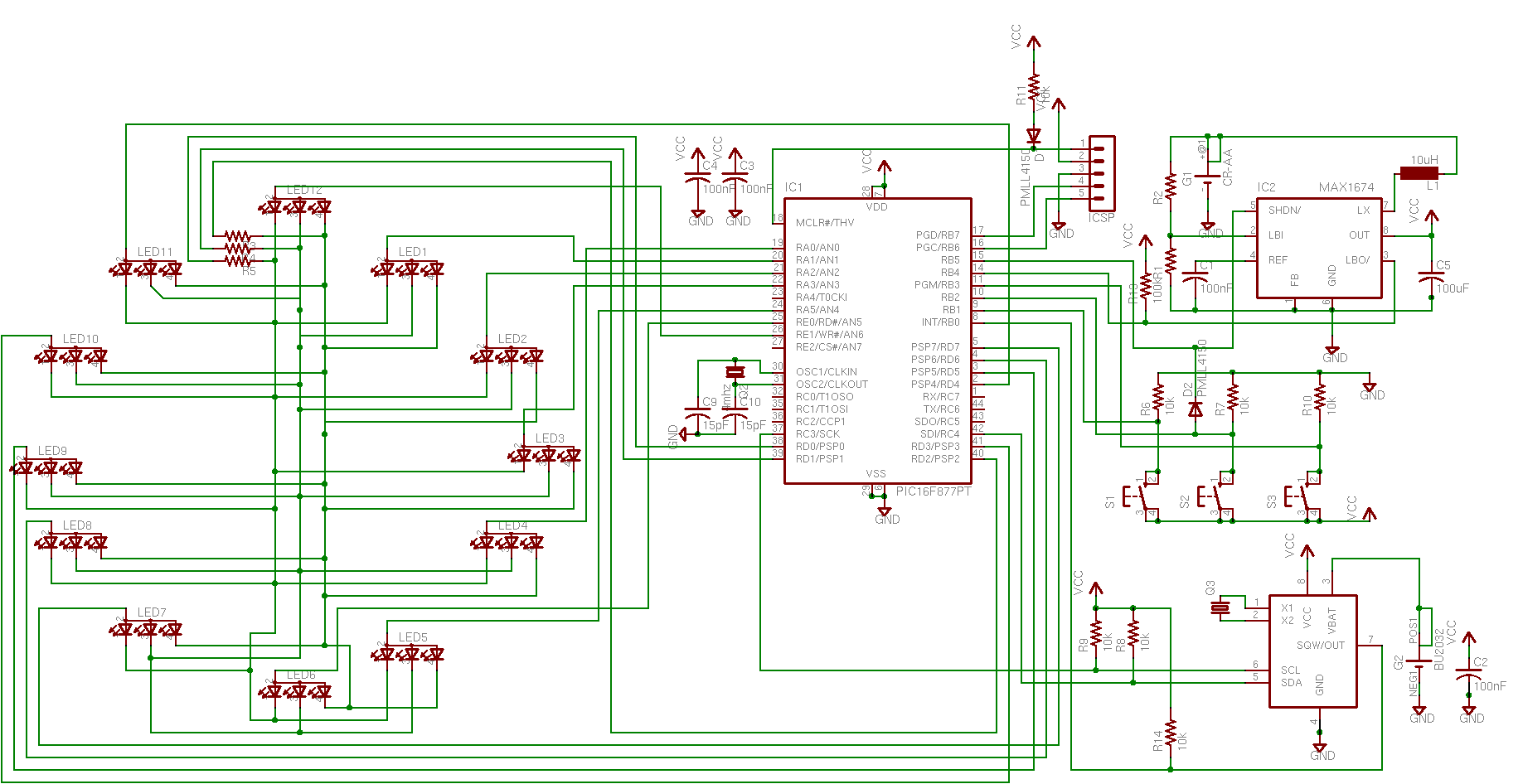
Replacing the driver board in an old-school door chime
The doorbell button was replaced with a lighted version, but the chime continued to sound after the button was pressed. These lighted buttons incorporate an incandescent bulb in parallel with the button, a component that has been modified in previous...
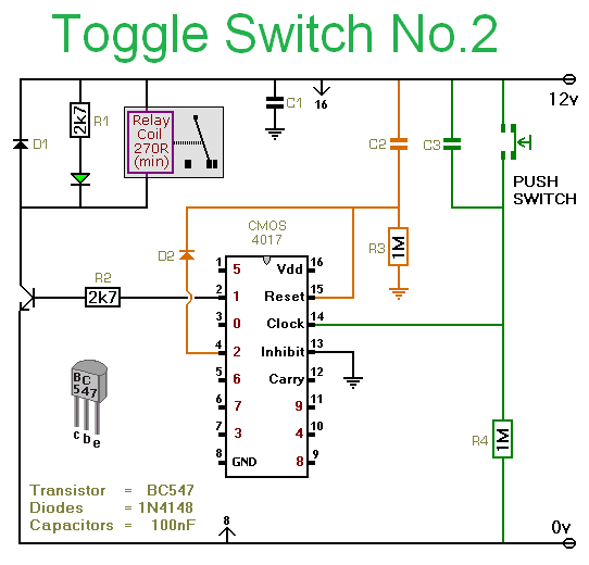
Toggle Switch with relay
Pushing the button once will energize the relay. Pushing the same button a second time will de-energize the relay. Any simple momentary action push-to-make switch will do. More: I've drawn the circuit with a single pole relay. But you can...
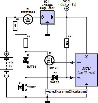
The Gentle Touch
Modern consumer appliances rarely include a conventional mains switch. Instead, these devices are activated and deactivated using a button on a remote control, similar to other functions. This circuit demonstrates how to control a device (provided it does not draw...