


Ethernet remote device controller sensor circuit
#ethernet
#microcontroller
#UDP
#TCP
#relay
#remote control
#Atmega88
#web browser
#device control
#automation
Description: The primary objective is to present the circuit diagram and describe the software utilized. A UDP application is employed to transmit commands to the microcontroller, which subsequently activates or deactivates the relay. It is anticipated that TCP implementation could also be feasible. The current UDP software occupies less than 3 kilobytes, which is significantly less than half of the memory capacity of an Atmega88. TCP would enable control of the device via a web browser; however, this has not yet been attempted. The circuit diagram provided is largely straightforward and adheres to standard configurations for the ENC28J60. The polarity of LED-B is crucial as it influences the duplex operation of the chip. Standard half-duplex operation is appropriate for a device that sends and receives minimal traffic. A relay can be connected to connector CONN3. It is important to note the presence of diode D1; it is intentionally oriented as shown in the circuit diagram. This diode serves a protective function for those intending to connect a small 6V relay to that output, safeguarding the entire circuit from potentially high voltages induced by the relay coil.
The circuit utilizes the ENC28J60 Ethernet controller, which provides a robust interface for network communications. The microcontroller, an Atmega88, is programmed to handle UDP packets, allowing for efficient command transmission and relay control. The design focuses on a half-duplex communication mode, which is suitable for applications with low traffic, thereby optimizing performance and minimizing the complexity of the circuit.
The inclusion of LED-B serves as an indicator of the operational status of the ENC28J60. Correct polarity is essential for proper functionality, as incorrect connections could lead to malfunction. The relay, connected through CONN3, is driven by the microcontroller's GPIO pin, enabling it to switch on or off based on received commands.
Diode D1 is a critical component in this circuit. It is placed in parallel with the relay coil and is oriented to allow current to flow in the reverse direction when the relay is deactivated. This action prevents voltage spikes, known as back EMF, which can occur when the relay coil is de-energized. Such spikes could potentially damage the microcontroller or other sensitive components within the circuit.
Overall, the design is aimed at providing a reliable and efficient means of controlling a relay through network commands, with considerations for both hardware protection and software efficiency. Future enhancements, such as TCP implementation, could further expand the functionality of this device, allowing for more versatile control options, including web-based interfaces.The main purpose is to show here the circuit diagram and explain the software. We use a UDP application to send commands to the microcontroller. Those commands will then cause the microcontroller to switch on or off the relay. It think it will be possible to even implement TCP. The current UDP software is less than 3k bytes and that is not even half of the memory on an Atmega88. TCP would then allow us to control the device via a web browser. I have however not tried it yet. Here is the circuit diagram. Most of it is very straight forward and standard for the ENC28J60. The polarity of LED-B is important as it determines the duplex operation of the chip. Standard Half-duplex is what makes most sense for a device which will send and receive only rather little traffic. A relay can be connected to connector CONN3. Note the diode D1. It is not useless and it is not the wrong way round in the circuit diagram even though it looks like that.
It is there for those who plan to connect a small 6V relay on that output. It protects the whole circuit against the possibly very high voltages which can be induced by the coil of a relay.
The circuit utilizes the ENC28J60 Ethernet controller, which provides a robust interface for network communications. The microcontroller, an Atmega88, is programmed to handle UDP packets, allowing for efficient command transmission and relay control. The design focuses on a half-duplex communication mode, which is suitable for applications with low traffic, thereby optimizing performance and minimizing the complexity of the circuit.
The inclusion of LED-B serves as an indicator of the operational status of the ENC28J60. Correct polarity is essential for proper functionality, as incorrect connections could lead to malfunction. The relay, connected through CONN3, is driven by the microcontroller's GPIO pin, enabling it to switch on or off based on received commands.
Diode D1 is a critical component in this circuit. It is placed in parallel with the relay coil and is oriented to allow current to flow in the reverse direction when the relay is deactivated. This action prevents voltage spikes, known as back EMF, which can occur when the relay coil is de-energized. Such spikes could potentially damage the microcontroller or other sensitive components within the circuit.
Overall, the design is aimed at providing a reliable and efficient means of controlling a relay through network commands, with considerations for both hardware protection and software efficiency. Future enhancements, such as TCP implementation, could further expand the functionality of this device, allowing for more versatile control options, including web-based interfaces.The main purpose is to show here the circuit diagram and explain the software. We use a UDP application to send commands to the microcontroller. Those commands will then cause the microcontroller to switch on or off the relay. It think it will be possible to even implement TCP. The current UDP software is less than 3k bytes and that is not even half of the memory on an Atmega88. TCP would then allow us to control the device via a web browser. I have however not tried it yet. Here is the circuit diagram. Most of it is very straight forward and standard for the ENC28J60. The polarity of LED-B is important as it determines the duplex operation of the chip. Standard Half-duplex is what makes most sense for a device which will send and receive only rather little traffic. A relay can be connected to connector CONN3. Note the diode D1. It is not useless and it is not the wrong way round in the circuit diagram even though it looks like that.
It is there for those who plan to connect a small 6V relay on that output. It protects the whole circuit against the possibly very high voltages which can be induced by the coil of a relay.
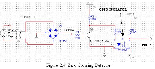
Industrial Building Automation System (IBAS) - 4
The two optical sensors will provide a count of individuals to the microcontroller, which will relay this value to MCU-II. The microcontroller will detect the entrance of any person through high-to-low pulse transitions on input pins A3 and A4.
The circuit...
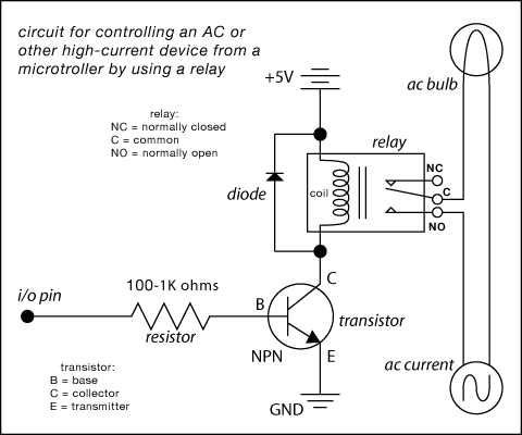
relay circuit diagram
Here are some circuit diagrams for driving relays from a microcontroller. Ensure the use of a 5-volt relay (this refers to the coil, not the load circuit) and verify that the relay has a sufficient rating for the load being...
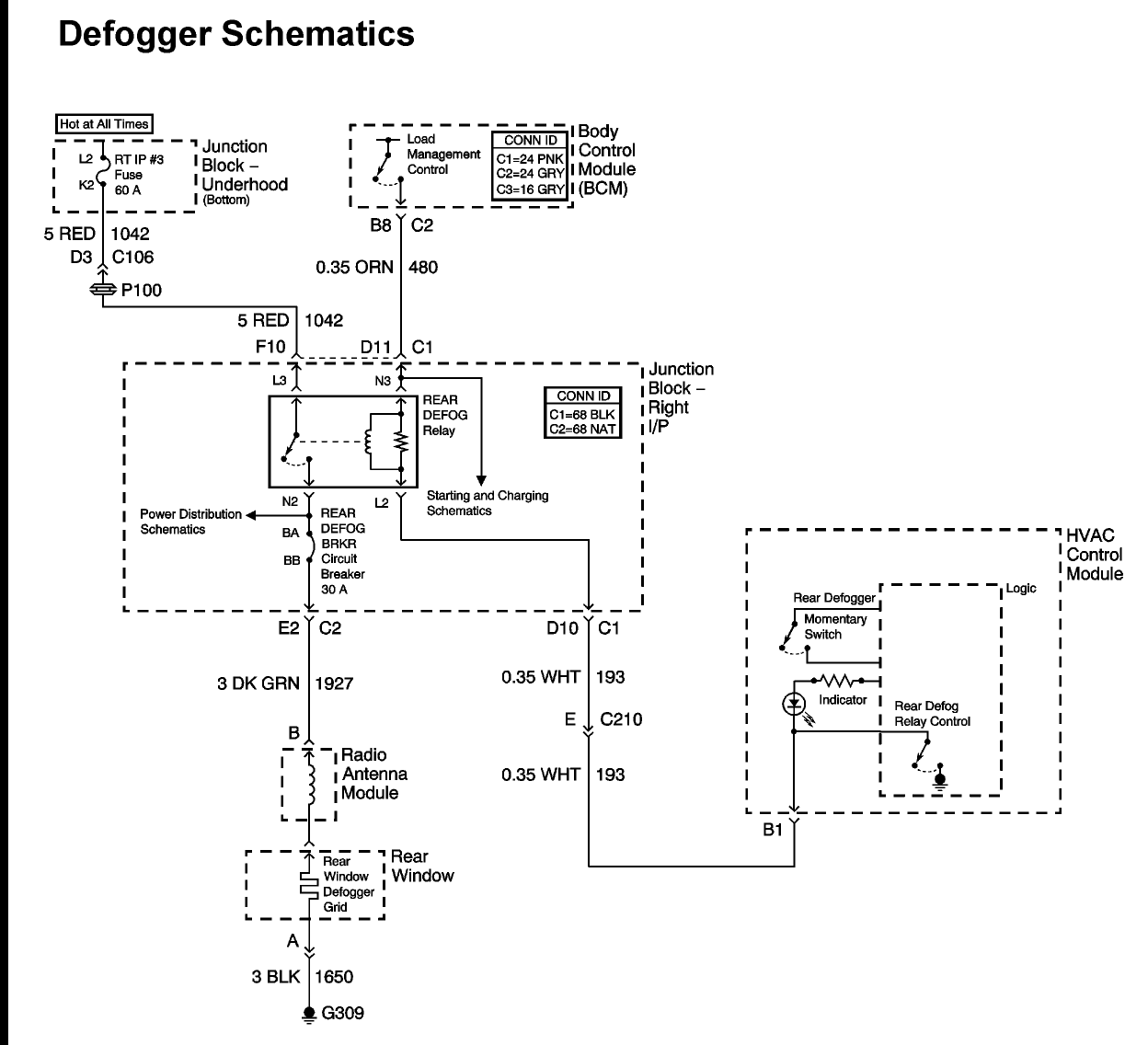
2004 chevy impala: relay diagram passenger side fuse block
A 2004 Chevrolet Impala is experiencing issues with the rear defogger. The owner is unable to locate the fuse for the rear defogger, although the relay has been found. Both the manual and the vehicle's diagram indicate a 30-amp fuse,...
build relay toggle switch
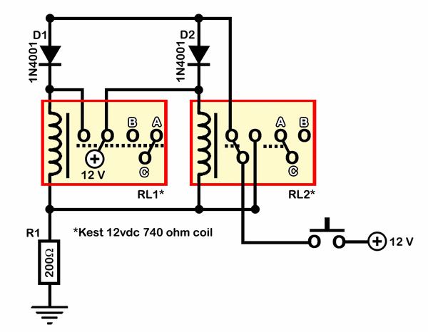
Half of RL1 and RL2 manage the switching mechanism, while the other half connects to an application. The relays operate at 200 ohms above ground, with one terminal referenced to positive voltage, which deactivates them. RL1, when off, applies a...
Photo Light with Relay
The circuit below uses a CMOS dual D flip flop (CD4013) to toggle a relay or other load with a momentary push button. Several push buttons can be wired in parallel to control the relay from multiple locations. More: The...
Reducing Relay Power Consumption
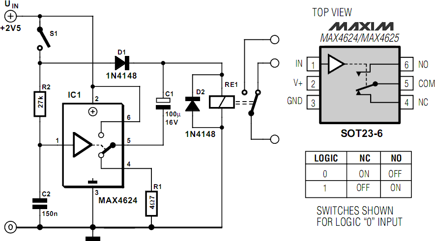
Relays are commonly utilized as electrically controlled switches. Unlike transistors, the switch contacts of relays are electrically isolated from the control input. However, the power dissipation in a relay coil can be undesirable for battery-operated applications. The incorporation of an...
Relay control circuit
The motor winding is configured with delta transposition capacitance, designated as cl-C-3G. It operates as a DC LAN speed generator and is associated with a three-phase asynchronous motor, which is coaxially connected through a field winding powered by a 10V...
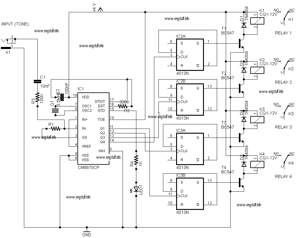
control of remote domestic system
This is a personal website showcasing various projects developed during spare time, many of which are related to electronics and Linux. The website itself is one of these projects. It also features a section with pictures from places visited and...
87C51 Selling Leads
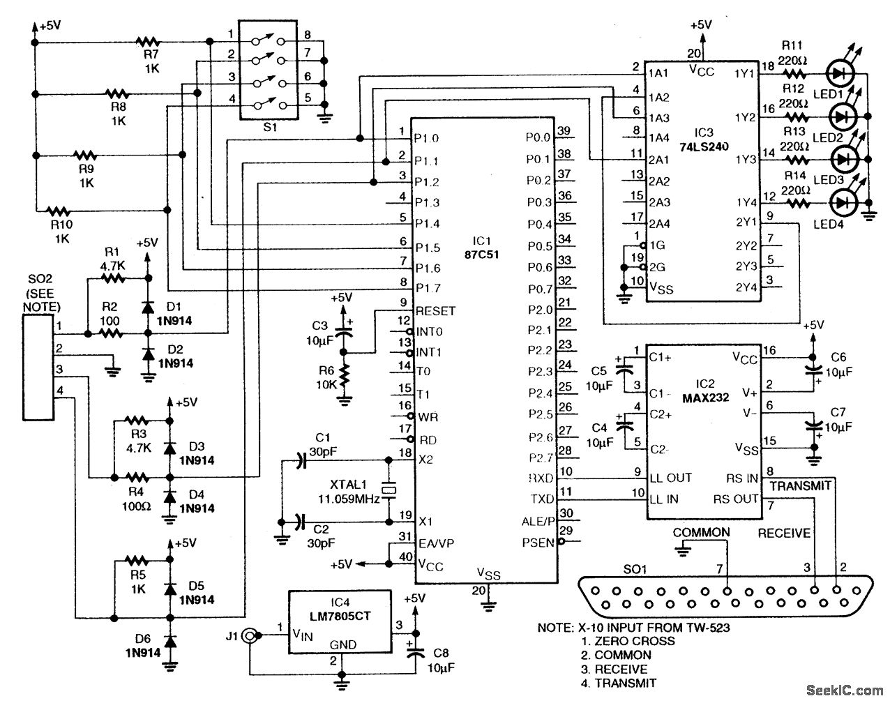
This circuit utilizes an 87C57 microcontroller along with several peripherals to convert X-10 power-line carrier-code formats from a personal computer for use with an X-10 power-line interface in a home control system. Software details can be found in the reference....