


Netzer Playground
#extension port
#LCD
#relays
#temperature sensor
#light sensor
#opto decoupled inputs
#Netzer
#socket
#plug
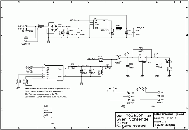
Description: The extension port plays a crucial role in the system. Depending on the application, various extension boards can be connected to the socket. Currently, extension boards for LCDs and domestic applications (such as relays, temperature and light sensors, and opto-isolated inputs) are under development. Sheet 1 illustrates the slot for the Netzer and the extension port. The Netzer can be either soldered directly or connected via sockets. All I/O pins of the Netzer are safeguarded against high input currents with series 100 Ω resistors. The SW_Reset function pulls the Netzer reset pin to ground, generating a system reset for both the Netzer and any potentially connected board at the extension port, which can be connected via two 10-pin headers with a 2 mm pitch. The Netzer is powered by a previously generated 3.3V supply. To ensure a versatile Extension Port, all Netzer pins and available voltages (including SUP_AUX) are connected. Sheet 2 details the power supply configuration. The input voltage (ranging from 6V to 24V, AC or DC) entering through X401 is protected against reverse polarity (B401), electrostatic discharge (ESD, D401), and short circuits (F401). The voltage (SUP_AUX) is routed to the extension port. The upper section generates a stable 5V (+5V_AUX) from either DC or AC using the switching regulator IC4, in conjunction with D401, L401, and electrolytic capacitors C402 and C403. A switching regulator is selected for its capability to accommodate a wide input voltage range without the need for an additional heat sink. Alternatively, a Power-over-Ethernet (PoE) supply device (such as those from Silver Telecom) may be utilized. The 48V source voltage (POE_VA1, _VA2, _VB1, and _VB2) is drawn directly from the Netzer. The power supply generates +5V, which can be optionally galvanically isolated (Ag9050-S) or galvanically connected (Ag8005-S). Components L701, C701, and C702 are employed to maintain low ripple. Resistor R702 signals the PoE device regarding the power class required by the power sourcing equipment (Class 0, as outlined in Table 1). Diodes D701, D702, transistor T401, and resistor R401 are utilized for prioritized O-ring management of the PoE voltage for +5V_AUX. Transistor T401 is activated for +5V_AUX only when no PoE voltage is present through R401, giving PoE the highest priority. Resistor R701 (A for Ag9050, B for Ag8005) compensates for the voltage drop across D702, adjusting the PoE voltage to 5.2V. The voltage after T401 serves as the initial power supply of +5V, which can be switched through SW_P. The linear voltage regulator IC2 converts the +5V to 3.3V, with LED_P indicating this voltage. Sheet 3 presents the breakout components for testing Netzer I/O connections. All I/Os are linked to LEDs via drivers (IC5 and IC6), which serve as port state indicators. Resistors R5 and R6 regulate the LED current, and jumpers JP1 and JP2 allow for the deactivation of the LED drivers. Each I/O pin connects to the middle pin of a three-pole jumper, enabling a selection between a 10 kΩ pull-up (R1 and R3) or pull-down resistor (R2 and R4). The I/O pins SPI_CLK and SPI_MI are exceptions, as their pull-ups can be adjusted using potentiometers (R28 and R29) within a range of 1 kΩ to 11 kΩ, which is beneficial when utilizing the Netzer in I2C mode, as these resistors must be calibrated for the desired bus frequency. Additionally, the switches labeled SW_XX can ground any I/O, necessitating a configured Netzer input and an activated pull-up for their operation. The module dimensions are 134 mm x 90 mm, and all components are through-hole technology (THT) parts. The assembly difficulty level is estimated to be medium due to the number of components involved.
The circuit design incorporates a multi-functional extension port that facilitates the integration of diverse extension boards, enhancing the versatility of the Netzer module. The implementation of protective components such as diodes and resistors ensures the system's resilience against electrical faults, while the switching regulator provides efficient voltage regulation across varying input conditions. The breakout board design allows for straightforward testing and debugging of I/O functionalities, with visual indicators (LEDs) providing real-time feedback on port states. The flexibility afforded by adjustable pull-up/pull-down configurations and the inclusion of potentiometers for specific I/O lines further enhances the adaptability of the design for various applications. The overall layout and assembly considerations reflect a design that balances functionality with ease of use, making it suitable for a range of electronic applications.The extension port has an important role. Depending on the application several extension boards can be put in the socket. Extension boards for LCD and domestic (relays, temperatur and light sensors, opto decoupled inputs) are under development. Sheet 1 shows the slot for Netzer and extension port. The Netzer can be directly soldered or plugged in via sockets. All IO pins of Netzer are protected against high input currents with serial 100 © resistors. SW_Reset pulls the Netzer reset pin to ground and generates a system reset at the Netzer and at a potentially connected board at the extension port which can be plugged in via two 10-pin headers with 2 mm grid. Netzer is supplied with the 3. 3V generated before. For a flexible Extension Port all Netzer pins and all available voltages (also SUP_AUX, see below) are connected.
Sheet 2 shows the power supply. The input voltage (6 V 24 V, AC or DC) from X401 is protected against reverse polarity (B401), ESD (D401) and short circuits (F401). The voltage (SUP_AUX) is connected to the extension port. The upper part generates from DC or AC with the switching regulator IC4 (in combination with D401, L401 and electrolytes C402 and C403) a stable 5V (+5V_AUX).
A switching regulator was chosen for a wide voltage input range. An extra heat sink is not required. Alternatively, a Power-over-Ethernet supply device (Silver Telecom ones are used here) can be mounted. The 48V source voltage (POE_VA1, _VA2, _VB1 and _VB2) is picked directly from Netzer. The power supply generates +5V (optional galvanically isolated Ag9050-S or galvanically connected Ag8005-S).
L701, C701 and C702 are used for low ripple. R702 is a resistance indicating the PoE-device the power class required for the power sourcing equipment (Class 0, see Table 1). D701, D702, T401 and R401 are used for prioritized O-ring of the PoE voltage for +5V_AUX. Transistor T401 is open for +5V_AUX only if there is no PoE voltage via R401. PoE has the highest priority. R701 (A for Ag9050, B for Ag8005) compensates the voltage drop of D702 - the PoE voltage is adjusted to 5.
2V. The voltage behind T401 is the first power supply of +5V switchable through SW_P. The linear voltage regulator IC2 converts the +5V to 3. 3V. LED_P indicates this voltage. Sheet 3 shows the Breakout parts for testing Netzer IOs. All IOs are connected to LEDs via driver (IC5 and IC6). The LEDs are used as port state indicators. R5 and R6 adjust the LED current. With jumpers JP1 and JP2 the LED drivers can be deactivated as well. Each IO pin is connected to the middle pin of a three-pole jumper. A jumper bridge chooses between a 10 k © pull-up (R1 and R3) or pull-down resistor (R2 and R4). The IOs SPI_CLK and SPI_MI are an exception because their pull-ups can be adjusted by a potentiometer (R28 and R29) in a range between 1 k © 11 k ©. That can be useful if the Netzer I2C mode is used. In that mode the resistors have to be adjusted for an intended bus frequency. Last but not least the switches named SW_XX can pull any IO to ground. A configured Netzer input and an activated pull-up are necessary for using these switches. The module has the dimensions 134mm x 90mm. All delivered parts are THT parts. The level for assembly is estimated as medium difficult, because of the amount of parts to assemble.
The circuit design incorporates a multi-functional extension port that facilitates the integration of diverse extension boards, enhancing the versatility of the Netzer module. The implementation of protective components such as diodes and resistors ensures the system's resilience against electrical faults, while the switching regulator provides efficient voltage regulation across varying input conditions. The breakout board design allows for straightforward testing and debugging of I/O functionalities, with visual indicators (LEDs) providing real-time feedback on port states. The flexibility afforded by adjustable pull-up/pull-down configurations and the inclusion of potentiometers for specific I/O lines further enhances the adaptability of the design for various applications. The overall layout and assembly considerations reflect a design that balances functionality with ease of use, making it suitable for a range of electronic applications.The extension port has an important role. Depending on the application several extension boards can be put in the socket. Extension boards for LCD and domestic (relays, temperatur and light sensors, opto decoupled inputs) are under development. Sheet 1 shows the slot for Netzer and extension port. The Netzer can be directly soldered or plugged in via sockets. All IO pins of Netzer are protected against high input currents with serial 100 © resistors. SW_Reset pulls the Netzer reset pin to ground and generates a system reset at the Netzer and at a potentially connected board at the extension port which can be plugged in via two 10-pin headers with 2 mm grid. Netzer is supplied with the 3. 3V generated before. For a flexible Extension Port all Netzer pins and all available voltages (also SUP_AUX, see below) are connected.
Sheet 2 shows the power supply. The input voltage (6 V 24 V, AC or DC) from X401 is protected against reverse polarity (B401), ESD (D401) and short circuits (F401). The voltage (SUP_AUX) is connected to the extension port. The upper part generates from DC or AC with the switching regulator IC4 (in combination with D401, L401 and electrolytes C402 and C403) a stable 5V (+5V_AUX).
A switching regulator was chosen for a wide voltage input range. An extra heat sink is not required. Alternatively, a Power-over-Ethernet supply device (Silver Telecom ones are used here) can be mounted. The 48V source voltage (POE_VA1, _VA2, _VB1 and _VB2) is picked directly from Netzer. The power supply generates +5V (optional galvanically isolated Ag9050-S or galvanically connected Ag8005-S).
L701, C701 and C702 are used for low ripple. R702 is a resistance indicating the PoE-device the power class required for the power sourcing equipment (Class 0, see Table 1). D701, D702, T401 and R401 are used for prioritized O-ring of the PoE voltage for +5V_AUX. Transistor T401 is open for +5V_AUX only if there is no PoE voltage via R401. PoE has the highest priority. R701 (A for Ag9050, B for Ag8005) compensates the voltage drop of D702 - the PoE voltage is adjusted to 5.
2V. The voltage behind T401 is the first power supply of +5V switchable through SW_P. The linear voltage regulator IC2 converts the +5V to 3. 3V. LED_P indicates this voltage. Sheet 3 shows the Breakout parts for testing Netzer IOs. All IOs are connected to LEDs via driver (IC5 and IC6). The LEDs are used as port state indicators. R5 and R6 adjust the LED current. With jumpers JP1 and JP2 the LED drivers can be deactivated as well. Each IO pin is connected to the middle pin of a three-pole jumper. A jumper bridge chooses between a 10 k © pull-up (R1 and R3) or pull-down resistor (R2 and R4). The IOs SPI_CLK and SPI_MI are an exception because their pull-ups can be adjusted by a potentiometer (R28 and R29) in a range between 1 k © 11 k ©. That can be useful if the Netzer I2C mode is used. In that mode the resistors have to be adjusted for an intended bus frequency. Last but not least the switches named SW_XX can pull any IO to ground. A configured Netzer input and an activated pull-up are necessary for using these switches. The module has the dimensions 134mm x 90mm. All delivered parts are THT parts. The level for assembly is estimated as medium difficult, because of the amount of parts to assemble.
Temperature Sensor
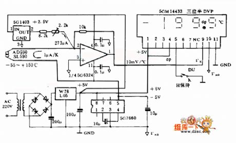
The LM35 temperature sensor provides an output of 10 mV/°C for every degree Celsius over 0°C. At 20°C, the output voltage is 20 x 10 = 200 mV. The circuit consumes 60 µA. The load resistance should not be less...
light intensity meter
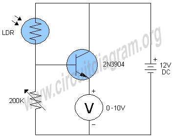
This simple light intensity meter circuit can be used to determine the intensity of light in a wide variety of electronic projects and experiments.
The light intensity meter circuit is designed to measure ambient light levels and can be employed in...
Voltage Levels Control Relays
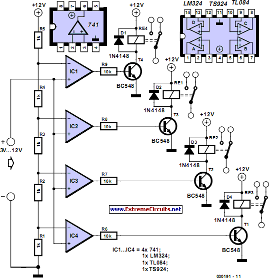
This circuit demonstrates that microprocessors, PCs, and modern ultra-accurate Digital-to-Analog Converters (DACs) are excessive for controlling four relays in sequence based on a control voltage ranging from 2.4 V to 12 V. By utilizing equal resistors in a ladder network...
Light Level Droplets Detector
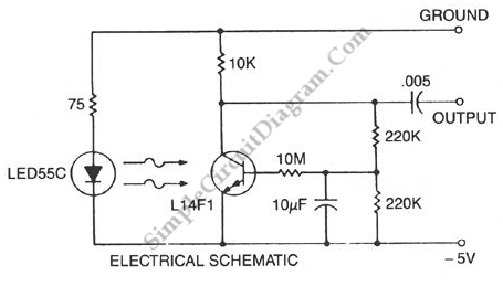
This circuit is a Low-Light Level Drop Detector. It utilizes a self-biasing configuration to detect small changes in light levels.
The Low-Light Level Drop Detector circuit is designed to sense minute variations in ambient light conditions, making it suitable for applications...
LCD contrast controlled by LCD
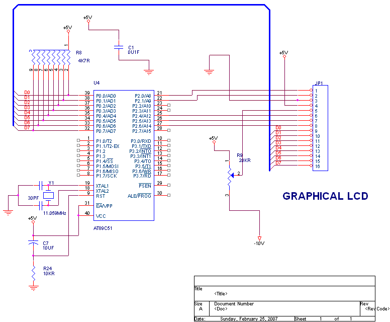
What is the recommended frequency for the Low Pass Filter used to control the contrast of an LCD? I want to adjust the contrast of an LCD using PWM.
To effectively control the contrast of an LCD using Pulse Width Modulation...
Fastest Finger First project
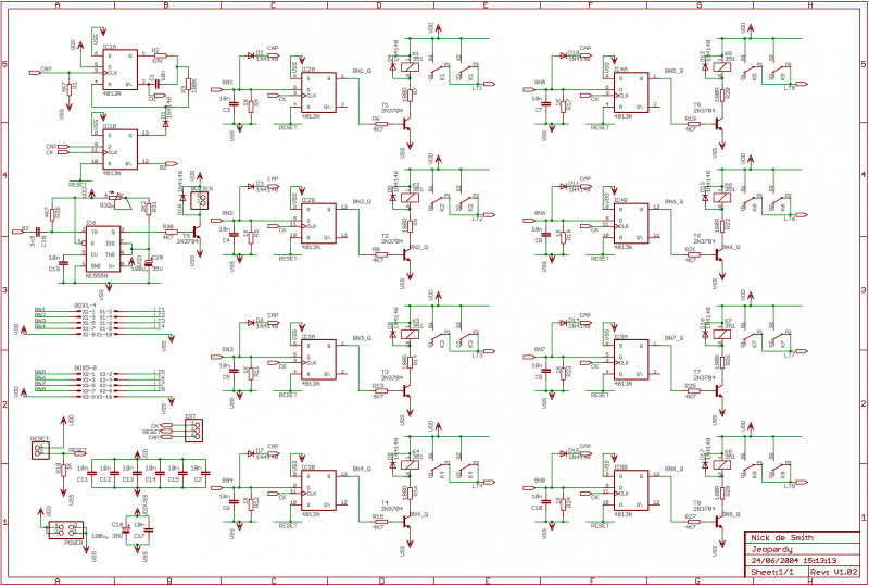
If 12V relays are used, you can replace the 180R resistors R7, R9, R14, R16, R20, R22, R26, and R28 with a wire link (the resistors are only there to limit current if you use 5V relays, of which I...
IR auto digital thermostat
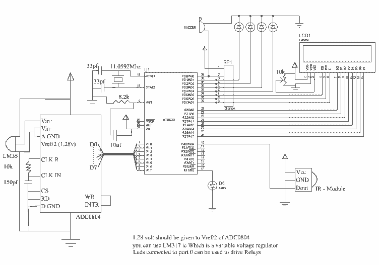
This circuit measures temperature in Celsius scale and displays it on an alphanumeric LCD screen. When temperature rises to 40°C, an alarm is activated and at the same time a relay is also activated which drives a fan to keep...

thermometer circuit
When the system is placed in a shop or mall, logos and product advertisements serve as an ideal complement to temperature information. For home use, photographs of children at the beach or, should the temperature drop, images of making a...

schematic how to write data on lcd
In the project, the LCD data ports are connected to port 1 of the controller, while the control pins, namely RS, E, and R/W, are connected to pins 3, 5, 6, and 2, 1 of the controller. The LCD is...